Allen-Bradley
RFQ Ready
Allen-Bradley 1747-L542 PLC Controller Module
SLC 500
Origin US
PLC Controller Module
Request verified availability, condition, replacement risk review, packing options and courier lead time for 1747-L541/C.
Click Request Quote and the part number is inserted into the inquiry form automatically.
Core fields for model confirmation and RFQ routing. Detailed product narrative remains below.
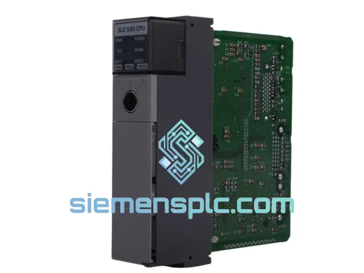
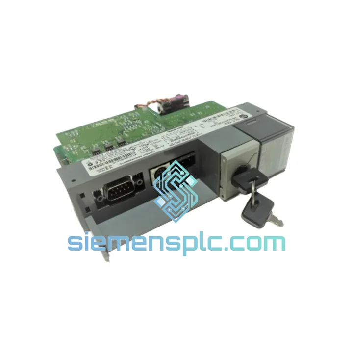
The Allen-Bradley 1747-L541/C is a Series C revision CPU module designed for Rockwell Automation’s SLC 500 modular programmable controller platform. Installed exclusively in the leftmost slot of a 1746-series chassis, this processor functions as the sole backplane bus master — executing user ladder logic, managing the input/output image table, and arbitrating all data exchange with installed 1746-series I/O modules. Its 16,384-word (16K) user program memory accommodates complex discrete and process control applications, while its dual-port communication architecture supports simultaneous RS-232 and DH-485 connectivity without auxiliary communication modules.
The 1747-L541/C operates within a modular chassis ecosystem spanning the 1746-A4 (4-slot) through 1746-A13 (13-slot) configurations, enabling I/O capacity from a minimum of 3 I/O slots up to 4,096 discrete points when expanded across multiple chassis via remote I/O adapters. The processor draws logic power from the chassis 5 VDC backplane bus, supplied by a 1746-P series power supply, and does not require a separate field-side power connection. This clean separation between logic-level and field-level power domains is a deliberate architectural choice that simplifies panel wiring and reduces the risk of field transients propagating into the CPU’s logic circuitry.
In a closed-loop control architecture, the 1747-L541/C executes a three-phase synchronous scan: (1) input image table refresh — the CPU polls each installed I/O module sequentially across the backplane and copies current input states into the input image table in RAM; (2) program execution — the ladder logic program is scanned rung-by-rung using the frozen input image, computing output coil states without reading live input data mid-scan; (3) output image table write — computed output states are transferred from the output image table to the physical output modules. This architecture guarantees that all logic decisions within a single scan are based on a temporally consistent input snapshot, a property critical for interlock circuits where simultaneous input transitions must be evaluated as a coherent state rather than a sequence of asynchronous events.
Typical scan time for the 1747-L541/C is approximately 1 ms per 1,000 words of ladder logic under normal operating conditions. For a fully populated 16K program, worst-case scan time remains within 16–20 ms, well within the response requirements of most discrete manufacturing and infrastructure automation applications. The processor’s internal watchdog timer, configurable via S:30 in the status file, enforces a maximum scan time ceiling — if the user program fails to complete within the configured interval, the CPU halts execution and asserts a major fault, preventing undefined output states from persisting in safety-critical circuits.
Real-time Stock & RFQ: [email protected] | WhatsApp: +86 18359268345
| Parameter | Specification |
|---|---|
| Catalog Number | 1747-L541/C |
| Platform | SLC 500 Modular |
| Series Revision | Series C |
| User Program Memory | 16,384 words (16K) |
| Data Table Memory | Shared within 16K word address space |
| Maximum I/O Points (local) | 4,096 discrete; analog per module specification |
| Scan Time | ~1 ms per 1K ladder words (typical) |
| Channel 0 Protocol | RS-232: DF1 Full Duplex, DF1 Half Duplex, ASCII, DH-485 (via 1747-KF3) |
| Channel 1 Protocol | DH-485: up to 31 nodes, 1.2 / 2.4 / 9.6 / 19.2 kbps selectable |
| Backplane Bus Voltage | 5 VDC (sourced from 1746-P chassis power supply) |
| Operating Temperature | 0 °C to +60 °C |
| Storage Temperature | −40 °C to +85 °C |
| Relative Humidity | 5% to 95%, non-condensing |
| Vibration (operational) | 2 g, 10–500 Hz per IEC 68-2-6 |
| Shock (operational) | 30 g; non-operational: 50 g |
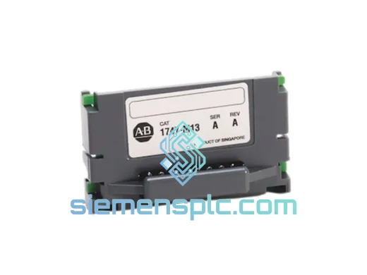
| Compatible Chassis | 1746-A4, 1746-A7, 1746-A10, 1746-A13 |
| Compatible Power Supplies | 1746-P1, P2, P3, P4, P7 |
| Programming Software | RSLogix 500 v1.0 and later |
| Certifications | UL Listed, CE Marked, CSA Certified, cUL |
| Warranty | 12 months from shipment date |
Backplane Bus Mastering and Slot-Poll Arbitration: The 1747-L541/C implements a strict master-only backplane protocol. No installed I/O module can initiate a data transfer; all backplane transactions are initiated exclusively by the CPU during the input-scan and output-write phases. The processor addresses each occupied slot in ascending order, issuing a read request to input modules and a write command to output modules. This deterministic polling sequence bounds the maximum I/O update latency to a calculable value: (number of occupied slots) × (per-slot transaction time), typically 50–200 µs per slot depending on module type. The absence of bus arbitration overhead — inherent in multi-master bus architectures — eliminates the latency jitter that would otherwise complicate time-sensitive output sequencing.
SRAM Memory Architecture with Battery-Backed Retention: Program and data table memory reside in static RAM backed by an onboard lithium battery. The battery maintains memory contents during power interruptions without requiring the user program to execute explicit save routines. Timer accumulated values (TA), counter accumulated values (CA), and integer file data persist across unplanned shutdowns, preserving production counters and process state variables that would otherwise require manual re-initialization after each power cycle. Battery condition is monitored by the processor and reported via the S:2/14 status bit, enabling predictive maintenance before memory loss occurs.
Optical Isolation Boundary at the I/O Module Layer: The CPU’s logic circuitry operates entirely at 5 VDC CMOS levels and does not interface directly with field-side voltages. All field signal termination — whether 24 VDC discrete, 120 VAC, 4–20 mA analog, or thermocouple — occurs at the 1746-series I/O module layer, where optical isolators rated at a minimum of 1,500 VAC provide galvanic separation between field wiring and backplane logic. This isolation architecture means that field-side wiring faults, including ground loops, inductive kickback from solenoid coils, and common-mode noise from variable frequency drives, are attenuated at the module boundary before any signal reaches the CPU’s data bus.
Fault Register Architecture and Diagnostic Transparency: The processor maintains a structured fault log within the S-file (status file, file 2). Major fault codes are written to S:6, minor fault codes to S:7, and the fault timestamp — derived from the internal real-time clock — is recorded in S:28 and S:29. Major faults (watchdog timeout, memory checksum error, I/O module communication failure) force the CPU into a faulted halt state with the FAULT LED illuminated, while minor faults are logged without halting execution, allowing the user program to implement fault-tolerant responses via the minor fault bits in S:5. This two-tier fault classification enables maintenance engineers to distinguish between conditions requiring immediate shutdown and those permitting continued operation with degraded functionality.
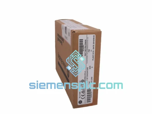
Each 1747-L541/C unit dispatched from our Xiamen, China facility is sourced through verified supply channels with documented component traceability. Before shipment, every module passes a structured pre-dispatch inspection: physical examination of PCB condition, backplane connector pin integrity, and original Rockwell Automation label authenticity; power-on boot sequence verification with LED status confirmation; and communication port continuity testing on both Channel 0 and Channel 1. Any unit showing evidence of remarking, repackaging, non-original firmware, or counterfeit labeling is rejected and removed from inventory.
All units are covered by a 12-month warranty against defects in materials and workmanship from the date of shipment. Warranty replacement dispatch targets 3 business days from receipt of the defective unit. Certificate of Conformance (CoC) and pre-shipment test records are available upon request to support ISO 9001 and internal quality-system documentation requirements.
Air freight from Xiamen reaches Europe, North America, Southeast Asia, and the Middle East in 3–7 business days under standard service. Express options via DHL, FedEx, and UPS achieve 1–3 business day delivery to most destinations. Each shipment includes commercial invoice, packing list, and country-of-origin certificate for customs clearance. Trade terms available: EXW Xiamen, FOB Xiamen, CIF destination port — specify preferred Incoterm at order placement.
Email: [email protected]
WhatsApp: +86 18359268345
Web: siemensplc.com
Location: Xiamen, China
© 2026 siemensplc.com. All rights reserved.
We check the full part number, brand, series and visible nameplate information before quotation.
Sales confirms stock path, condition option, quantity and realistic lead time for export dispatch.
DHL, FedEx, UPS or buyer courier arrangements can be reviewed with packing requirements.
Similar brand or category products for fast comparison and multi-item RFQ lists.