Allen-Bradley
RFQ Ready
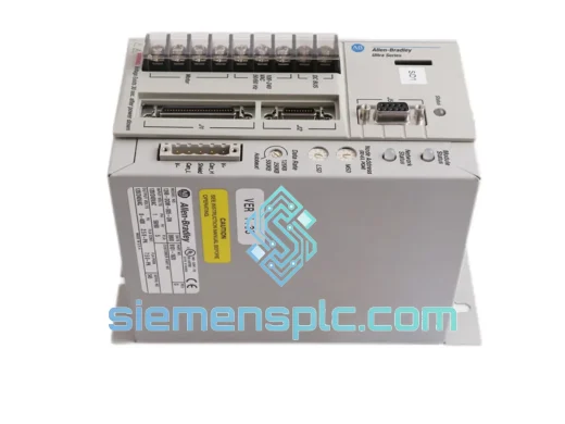
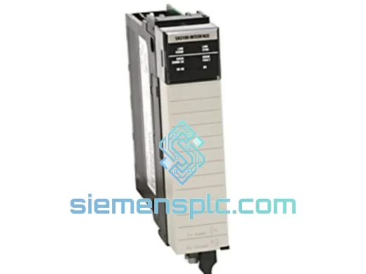
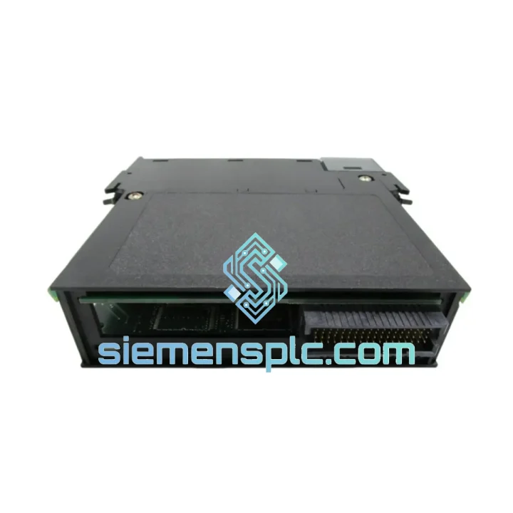
Allen-Bradley 1756-DMF30 Drive Module – ControlLogix
ControlLogix
Origin US
Drive Module
Request verified availability, condition, replacement risk review, packing options and courier lead time for 1756-DMD30.
Click Request Quote and the part number is inserted into the inquiry form automatically.
Core fields for model confirmation and RFQ routing. Detailed product narrative remains below.
In high-inertia drive applications — steel rolling mill coilers, extruder gearbox drives, centrifuge spin-up sequences — the command path between the PLC scan cycle and the drive inverter gate signal is the single most consequential latency source in the control loop. The Allen-Bradley 1756-DMD30 addresses this at the hardware layer. It is a single-slot 1756 chassis module that places the drive communication interface directly on the ControlLogix backplane, binding drive command delivery to the controller’s scheduled task clock rather than to the probabilistic timing of a network protocol stack.
The architectural distinction from EtherNet/IP-based drive integration is not marginal. A network-mediated path introduces variable latency at each hop: the controller’s Ethernet port transmit queue, the managed switch forwarding table lookup, the drive adapter’s protocol parser, and the inverter’s command register write cycle. Under normal network load these delays may total 3 ms to 8 ms; under congestion they are unbounded. The 1756-DMD30 eliminates every one of these hops. The drive command register is written by the backplane arbiter within the same scheduled window as the controller’s I/O scan — a fixed, verifiable interval that does not change with network topology or traffic load.
For coordinated multi-axis applications where speed reference skew between drives must be held below 1 ms — web tension control, draw ratio regulation, synchronous winding — this is not a performance preference. It is a functional requirement that network-based integration cannot reliably satisfy without dedicated real-time Ethernet infrastructure. The 1756-DMD30 satisfies it by construction, using the backplane’s hardware-scheduled arbitration as the synchronization mechanism.
The module maps drive data into the Logix 5000 native DRIVE tag structure. Speed reference, torque reference, control word, and status word appear as typed tag members in the controller’s tag database, accessible from any routine in the Logix program without add-on instruction development. Commissioning engineers work entirely within Studio 5000 Logix Designer, applying the same structured text or ladder logic used for all other 1756 I/O. There is no secondary programming environment, no gateway configuration utility, and no protocol mapping table to maintain across firmware updates.
The module occupies one standard 1756 chassis slot and draws 130 mA from the 5 VDC backplane rail — a power budget that does not require chassis power supply upsizing in typical configurations. It supports Removal and Insertion Under Power (RIUP), allowing hot-swap replacement with the connected drive in a safe stopped state, without de-energizing the chassis or interrupting adjacent control loops.
Real-time Stock & RFQ: [email protected] | WhatsApp: +86 18359268345
| Parameter | Specification |
|---|---|
| Catalog Number | 1756-DMD30 |
| Platform | Allen-Bradley ControlLogix 1756 |
| Module Classification | Drive Communication Module |
| Chassis Slot Occupancy | 1 slot (standard 1756 form factor) |
| Backplane Supply Current | 130 mA @ 5 VDC |
| Maximum Power Dissipation | 0.65 W |
| Backplane-to-Drive Isolation | Optical isolation (galvanic separation) |
| Operating Temperature Range | 0 °C to +60 °C |
| Storage Temperature Range | -40 °C to +85 °C |
| Relative Humidity | 5% to 95%, non-condensing |
| Vibration Compliance | IEC 60068-2-6 |
| Shock Compliance | IEC 60068-2-27 |
| EMC Certification | CE Marked — EMC Directive 2014/30/EU |
| Safety Listing | UL Listed |
| RoHS Compliance | Compliant |
| IEC Standard | IEC 61131-2 |
| RIUP Support | Yes — Removal and Insertion Under Power |
| Compatible Drive Families | PowerFlex series (refer to PFLEX-SG002 selection guide) |
| Compatible Processors | ControlLogix 5570 (1756-L7x), 5580 (1756-L8xE) |
| Module Weight | Approx. 300 g |
| Warranty Period | 12 months from shipment date |
The 1756-DMD30’s internal signal chain begins at the backplane edge connector, where a dedicated backplane communication controller — clocked synchronously with the ControlLogix chassis arbiter — receives scheduled data frames from the CPU module. The arbiter allocates a fixed time slot to each installed I/O module per scan cycle; the 1756-DMD30’s slot assignment is established at chassis power-up and does not change during operation. This means the maximum time between a controller tag write and the corresponding drive command register update is deterministic and calculable from the configured task period — a property that cannot be guaranteed in any network-mediated architecture.
Between the backplane interface and the drive-side output circuitry, the module inserts an optically isolated coupling stage. The isolation barrier serves a specific EMC function in VFD-dense control panels: PWM switching at the drive output stage generates common-mode conducted emissions that propagate along the ground plane of the control cabinet. Without galvanic separation, these emissions couple into the backplane ground reference, introducing noise into the analog and digital I/O circuits of every module in the chassis. The optical isolator breaks this coupling path at the module boundary, confining drive-generated noise to the drive-side circuit and preserving backplane signal integrity.
The drive-side interface implements the Logix 5000 DRIVE tag protocol natively. The protocol frame carries a 16-bit control word, a 32-bit speed reference (in engineering units scaled to the drive’s rated speed), a 32-bit torque reference, and a 32-bit status word. These fields map directly to controller tag members without intermediate encoding or decoding. The absence of a protocol translation layer eliminates the jitter contribution that accumulates in gateway architectures — typically 0.5 ms to 2 ms per translation stage — and removes the firmware dependency between the gateway’s protocol parser version and the drive’s adapter firmware revision.
PCB layout follows multilayer construction with continuous ground planes on inner layers flanking the high-frequency backplane signal traces. This stackup minimizes the loop area of backplane signal return paths, reducing radiated emissions from the module itself and improving immunity to external field sources. The 1756 keying mechanism on the backplane connector provides a passive hardware interlock: the module’s key code matches only the drive communication slot type, preventing installation in an incompatible slot position without requiring software validation at startup.
Each Allen-Bradley 1756-DMD30 unit dispatched from siemensplc.com passes a structured pre-shipment verification sequence. Physical inspection covers PCB surface condition, backplane connector pin geometry, label print quality and adhesion, and housing for any indicators inconsistent with genuine Rockwell Automation manufacturing. Catalog number, series letter, and firmware revision are confirmed against Rockwell’s published revision matrix before the unit is released to packaging.
Where bench test infrastructure is available, modules are installed in a powered 1756 chassis and queried via Studio 5000 to confirm backplane recognition, module identity response, and firmware revision readback. Units that fail any verification stage are quarantined and excluded from shipment inventory.
All shipments originate from Xiamen, China — a primary international freight hub with established express carrier connections to Southeast Asia, the Middle East, Europe, and North America. Standard export documentation accompanies every international order: commercial invoice, packing list, and certificate of conformance on request. DHL, FedEx, and UPS express services are used for time-sensitive orders, with shipment tracking provided from dispatch through final delivery. HS code classification and export compliance are managed by our logistics team, reducing customs clearance delays at destination ports.
Units are packed in anti-static bags with closed-cell foam cushioning inside double-wall corrugated cartons. Catalog number, series, and revision are labeled on the outer carton surface to allow receiving inspection without unpacking. A 12-month warranty from the date of shipment covers manufacturing defects and confirmed functional failures under normal operating conditions as defined in Rockwell Automation publication 1756-TD001.
Email: [email protected]
WhatsApp: +86 18359268345
Web: siemensplc.com
Location: Xiamen, China
© 2026 siemensplc.com. All rights reserved.
{
“@context”: “https://schema.org/”,
“@type”: “Product”,
“name”: “Allen-Bradley 1756-DMD30 ControlLogix Drive Interface Module”,
“description”: “Allen-Bradley 1756-DMD30 single-slot ControlLogix 1756 drive communication module with backplane-scheduled command delivery, optical isolation, and native Logix 5000 DRIVE tag integration for PowerFlex drive families.”,
“sku”: “1756-DMD30”,
“mpn”: “1756-DMD30”,
“brand”: {
“@type”: “Brand”,
“name”: “Allen-Bradley”
},
“manufacturer”: {
“@type”: “Organization”,
“name”: “Rockwell Automation”
},
“category”: “Industrial Automation / PLC Drive Communication Modules”,
“countryOfOrigin”: “US”,
“offers”: {
“@type”: “Offer”,
“priceCurrency”: “USD”,
“availability”: “https://schema.org/InStock”,
“seller”: {
“@type”: “Organization”,
“name”: “siemensplc.com”,
“url”: “https://siemensplc.com”
}
}
}
We check the full part number, brand, series and visible nameplate information before quotation.
Sales confirms stock path, condition option, quantity and realistic lead time for export dispatch.
DHL, FedEx, UPS or buyer courier arrangements can be reviewed with packing requirements.
Similar brand or category products for fast comparison and multi-item RFQ lists.