Honeywell
RFQ Ready
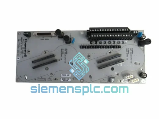
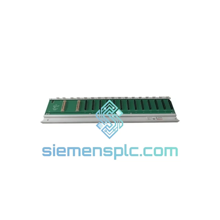
Honeywell 900H02-0202 Relay Digital Output Module
Origin US
Relay Digital Output Module
Request verified availability, condition, replacement risk review, packing options and courier lead time for 2MLR-E12P.
Click Request Quote and the part number is inserted into the inquiry form automatically.
Core fields for model confirmation and RFQ routing. Detailed product narrative remains below.
The Honeywell 2MLR-E12P is a 12-slot I/O expansion base engineered for the Modular Logic Relay (MLR) platform — a distributed relay-logic control architecture widely deployed in building automation, HVAC sequencing, and light industrial process control. Within an MLR control loop, the expansion base functions as the physical and electrical backbone that interconnects discrete I/O modules to the MLR master controller via a proprietary parallel backplane bus. Each of the 12 module slots provides a keyed edge connector that carries both the module power rail (24 V DC) and the bidirectional data lines used for cyclic I/O polling. The base itself does not perform logic execution; its role is deterministic signal routing — ensuring that scan-cycle data from field devices reaches the controller CPU without latency introduced by external wiring or intermediate terminal blocks.
Mechanically, the 2MLR-E12P is designed for 35 mm DIN rail mounting per EN 60715, with a snap-lock retention mechanism that prevents vibration-induced displacement in panel environments subject to mechanical shock up to IEC 60068-2-27 test conditions. The housing is constructed from UL 94 V-0 rated thermoplastic, providing self-extinguishing properties relevant to panel fire-safety compliance. At 540 g, the base is dimensioned to occupy a predictable panel footprint, allowing system designers to calculate cabinet space allocation with precision when scaling I/O density across multiple expansion bases.
From a signal integrity standpoint, the backplane traces within the 2MLR-E12P are impedance-controlled to minimize reflections at the module connector interface — a design consideration that becomes significant when the MLR system operates in environments with high-frequency switching noise from variable-frequency drives (VFDs) or large contactor banks. The ground plane architecture of the base provides a low-impedance reference path that supports the common-mode noise rejection of the I/O modules installed in its slots, complementing the optical isolation stages present in Honeywell MLR digital I/O modules.
System architects integrating the 2MLR-E12P into a control panel should account for the cumulative current draw of all installed modules against the base’s power distribution capacity. The 24 V DC bus on the backplane is rated to supply the aggregate module load; exceeding this threshold requires distributing I/O across multiple bases rather than overloading a single unit. This constraint also informs the selection of the MLR master controller’s power supply, which must be sized to cover both the controller’s own consumption and the downstream base-and-module load.
For maintenance and lifecycle management, the 2MLR-E12P supports hot-swap-compatible module removal in systems where the MLR controller firmware permits online I/O reconfiguration. This capability reduces planned downtime during module replacement or I/O expansion activities, a measurable operational benefit in facilities where control system availability directly impacts production throughput. The 12-month warranty coverage on this unit reflects confidence in the component’s manufacturing quality and provides procurement teams with a defined risk boundary for capital expenditure planning.
Real-time Stock & RFQ: [email protected] | WhatsApp: +86 18359268345
| Parameter | Specification |
|---|---|
| Part Number / SKU | 2MLR-E12P |
| Manufacturer | Honeywell |
| Product Series | Modular Logic Relay (MLR) |
| Module Slots | 12 |
| Mounting Standard | 35 mm DIN Rail (EN 60715) |
| Backplane Bus Voltage | 24 V DC |
| Housing Material | UL 94 V-0 Thermoplastic |
| Unit Weight | 540 g |
| Compatible Controllers | Honeywell MLR Series Master Controllers |
| Compatible Modules | MLR Digital I/O, Analog I/O, Communication Modules |
| Operating Temperature | 0 °C to +55 °C (storage: -40 °C to +85 °C) |
| Relative Humidity | 5% to 95% non-condensing |
| Shock Resistance | IEC 60068-2-27 |
| Condition | Genuine New / Factory Surplus New |
| Warranty | 12 months from date of shipment |
The 2MLR-E12P backplane operates on a synchronous polling architecture. The MLR master controller issues a cyclic scan command across the backplane bus at a fixed interval; each occupied slot responds with its current I/O state data within the allotted time window. This deterministic exchange model — as opposed to an event-driven interrupt architecture — ensures that the controller’s scan cycle time remains bounded and predictable regardless of field-side signal activity. For control engineers specifying response time budgets in HVAC sequencing or relay-logic interlock applications, this bounded latency is a quantifiable design parameter rather than a probabilistic estimate.
The slot keying mechanism on the 2MLR-E12P edge connectors enforces module-type compatibility at the physical layer, preventing incorrect module insertion that could corrupt backplane addressing or damage the power distribution traces. Each slot’s connector pin assignment separates the 24 V DC power pins from the data lines with a defined creepage distance, reducing the risk of power-to-signal cross-contamination under humid panel conditions.
EMC performance of the base is supported by the continuous ground plane that underlies the backplane PCB. This plane provides a return path for high-frequency transient currents induced by nearby switching devices, attenuating conducted emissions before they reach the module connector interface. In installations adjacent to VFD panels or large motor starters, this ground plane architecture measurably reduces the susceptibility of the I/O data bus to common-mode interference — a failure mode that manifests as spurious input state changes or communication timeouts in less robustly designed expansion bases.
The DIN rail snap-lock retention on the 2MLR-E12P uses a dual-latch design that requires deliberate downward pressure to release, preventing accidental dislodgement during panel vibration events. This mechanical retention characteristic is relevant in mobile or transportation-adjacent applications where panel assemblies may experience sustained low-frequency vibration outside the static installation envelope.
Every Honeywell 2MLR-E12P unit dispatched from our Xiamen, China facility is a genuine factory-origin component sourced through verified industrial supply channels. Prior to shipment, each unit undergoes physical inspection covering label integrity, part number and date code verification, connector pin condition, and housing integrity. Units presenting any evidence of remanufacture, relabeling, or non-factory repair are rejected and excluded from inventory.
Export documentation — including commercial invoice, packing list, and certificate of conformance upon written request — is prepared for each shipment to support customs clearance in destination markets across Asia-Pacific, Europe, the Middle East, and the Americas. Shipping is executed via DHL Express and FedEx International for time-sensitive orders, with sea freight consolidation available for volume procurement. Typical dispatch lead time for in-stock units is 3–5 business days from order confirmation. The 12-month warranty covers manufacturing defects and covers DOA (Dead on Arrival) replacement with traceable documentation.
Email: [email protected]
WhatsApp: +86 18359268345
Web: siemensplc.com
Location: Xiamen, China
© 2026 siemensplc.com. All rights reserved.
We check the full part number, brand, series and visible nameplate information before quotation.
Sales confirms stock path, condition option, quantity and realistic lead time for export dispatch.
DHL, FedEx, UPS or buyer courier arrangements can be reviewed with packing requirements.
Similar brand or category products for fast comparison and multi-item RFQ lists.