Bently Nevada
In Stock OK
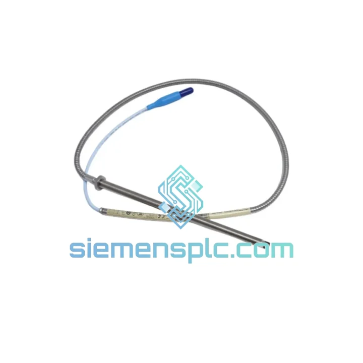
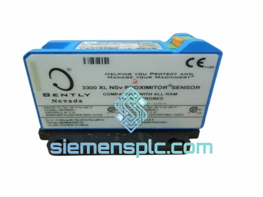
Bently Nevada 330104-00-20-15-12-05 Proximity Probe – 3300 XL Series
Request verified availability, condition, replacement risk review, packing options and courier lead time for 330104-00-20-15-12-05.
BrandBently Nevada
Part Number330104-00-20-15-12-05
ConditionAvailability Check
Lead TimeRFQ Confirmation
DocumentsDatasheet / photos by RFQ
ShippingExport packing available
Auto-filled RFQ
330104-00-20-15-12-05
Click Request Quote and the part number is inserted into the inquiry form automatically.
- Reply by email: [email protected]
- WhatsApp / Tel: +86 18359268345
- Mon-Sat 9:00-18:00 GMT+8
Procurement Data
Key Product Information
Core fields for model confirmation and RFQ routing. Detailed product narrative remains below.
- Brand
- Bently Nevada
- Primary Part Number
- 330104-00-20-15-12-05
- Product Type
- Proximity Probe
- Series / Family
- 3301
- Country of Origin
- US
- Catalog Category
- Sensors & Switches
- Warranty
- 12 months from date of shipment
- Compliance
- API 670 (5th Ed.), CE (EMC Directive 2014/30/EU), RoHS 2011/65/EU
Model confirmed for inquiry
330104-00-20-15-12-05
Send quantity, destination and urgency. The RFQ form keeps this part number attached.
Request Quote
Product Overview
Bently Nevada 330104-00-20-15-12-05: 8 mm Eddy-Current Proximity Probe for Shaft Displacement Measurement in Turbomachinery Protection Systems
The Bently Nevada 330104-00-20-15-12-05 is a factory-calibrated 8 mm eddy-current proximity probe within the 3300 XL Proximity System — a three-component measurement chain (probe, extension cable, proximitor/oscillator-demodulator) engineered to deliver continuous, non-contact shaft displacement data to machinery protection monitors. The part number encodes specific mechanical and electrical configuration: 8 mm probe body, 5 m integral armored cable, 15 ft (4.57 m) extension cable, standard armoring, and a defined connector termination. Each digit in the suffix is a functional specification, not a revision marker.
Within a closed-loop machinery protection architecture, this probe occupies the transducer position in the measurement chain. Its output — a DC voltage proportional to probe-to-shaft gap — feeds directly into Bently Nevada 3300 or 3500 series monitor cards, where the signal is processed for radial vibration amplitude, DC gap (shaft centerline position), and phase angle relative to a Keyphasor reference. The monitor card then executes alarm and trip logic based on configurable setpoints, with response times governed by the monitor’s filter settings rather than any limitation in the probe itself. The probe’s role is to deliver a low-noise, high-linearity analog signal across its calibrated gap range; all protection decision logic resides downstream.
Real-time Stock & RFQ: [email protected] | WhatsApp: +86 18359268345
Technical Parameters
| Parameter | Specification |
|---|---|
| Part Number | 330104-00-20-15-12-05 |
| Brand | Bently Nevada (Baker Hughes) |
| Series | 3300 XL Proximity System |
| Probe Tip Diameter | 8 mm |
| Integral Cable Length | 5 m (armored coaxial) |
| Extension Cable Length | 15 ft / 4.57 m |
| Total System Cable Length (max) | 9 m (probe + extension combined) |
| Oscillation Frequency (nominal) | ~1.0 MHz |
| Scale Factor | 200 mV/mil (7.87 V/mm) |
| Linear Measurement Range | 80–180 mil (2.03–4.57 mm) |
| Nominal DC Output Voltage | −18 VDC (at mid-range gap, matched proximitor) |
| Supply Voltage (via proximitor) | −24 VDC nominal |
| Target Material (factory cal.) | AISI 4140 steel |
| Operating Temperature — Probe Body | −35 °C to +177 °C |
| Operating Temperature — Extension Cable | −35 °C to +105 °C |
| Probe Housing Material | 316 stainless steel |
| Thread Size | M10 × 1.0 |
| Connector Termination | Integral coaxial, armored jacket |
| Compliance | API 670 (5th Ed.), CE (EMC Directive 2014/30/EU), RoHS 2011/65/EU |
| Warranty | 12 months from date of shipment |
Hardware Logical Analysis
Oscillator-Demodulator Circuit Interaction: The 330104-00-20-15-12-05 probe coil forms the inductive element of a Colpitts-type LC resonant circuit housed within the matched 3300 XL proximitor. At the nominal 1.0 MHz oscillation frequency, the coil radiates an electromagnetic field with a usable depth of penetration into the target of approximately 0.25 mm for AISI 4140 steel — sufficient to couple with the shaft surface without sensitivity to subsurface microstructure. As the shaft-to-probe gap decreases, eddy-current loading on the coil increases, reducing oscillator amplitude. The demodulator converts this amplitude variation to the DC output voltage at the specified 200 mV/mil scale factor. The linearity of this conversion across the 80–180 mil range is maintained within ±1% of full-scale output when total cable capacitance remains within the 9 m system length constraint.
Cable Capacitance and System Length Constraint: The 9 m maximum total cable length is not an arbitrary installation guideline — it is a hard electrical boundary. Coaxial cable capacitance (approximately 100 pF/m for the 3300 XL cable) loads the oscillator tank circuit. Exceeding 9 m shifts the oscillator operating point outside the demodulator’s linear region, producing a non-linear scale factor that cannot be corrected by proximitor adjustment. Field installations that require longer cable runs must use a signal conditioning amplifier at the proximitor output rather than extending the coaxial cable between probe and proximitor.
EMC Architecture — Coaxial Shielding Continuity: The integral armored cable provides a continuous coaxial shield from the probe body to the proximitor input connector. This shield is grounded at the proximitor end only (single-point grounding), preventing ground loop currents from injecting common-mode noise into the measurement signal. In installations adjacent to variable-frequency drives, high-voltage switchgear, or large motor starters, this single-point shield grounding scheme is the primary defense against conducted EMI. The shield’s mechanical armor layer additionally provides protection against physical damage in cable trays shared with power cabling — a common installation scenario in compressor trains and turbine packages.
Target Material Electromagnetic Properties: The eddy-current coupling coefficient is a function of target electrical conductivity (σ) and relative magnetic permeability (μr). AISI 4140 steel (σ ≈ 4.0 × 10⁶ S/m, μr ≈ 100 at low field) is the factory calibration standard. Austenitic stainless steels (e.g., 316L: σ ≈ 1.35 × 10⁶ S/m, μr ≈ 1.0) and nickel-base superalloys (e.g., Inconel 718: σ ≈ 0.8 × 10⁶ S/m) produce significantly different coupling, shifting the effective scale factor by 10–30% from nominal. Installations on non-standard shaft materials require a target material correction factor to be applied during proximitor calibration — a procedure defined in Bently Nevada Application Note 44 and required by API 670 Section 5.4.3.
Mechanical Mounting and Cable Fatigue Considerations: The M10 × 1.0 threaded probe body allows gap setting via locknut adjustment with a resolution of 1.0 mm per full rotation. The armored cable exits the probe body at a fixed radial angle; the minimum bend radius of the armored cable (typically 50 mm for the 3300 XL cable) must be maintained at the probe body junction. Installations that route the cable through a tight radius at the probe exit point introduce cyclic bending stress at the cable-to-probe junction — a fatigue failure mode that manifests as intermittent signal dropout before complete open-circuit failure. Bracket design must account for this constraint, particularly on machines with significant casing thermal growth between cold and operating conditions.
System Integration Benefits
- API 670 Fifth Edition Compliance Without Additional Validation: The 330104-00-20-15-12-05 is designed, tested, and documented to API Standard 670 (5th Edition) — the governing specification for non-contacting vibration measurement systems on critical rotating equipment. Procurement of this part number satisfies the instrumentation specification requirements for API 670-compliant machinery protection systems without requiring supplementary compliance testing or documentation from the end user.
- Direct Electrical Compatibility with 3300 and 3500 Monitor Cards: The −18 VDC nominal output at 200 mV/mil is the native input specification for Bently Nevada 3300/16, 3300/20, 3500/40M, and 3500/42M monitor cards. No signal conditioning, impedance matching, or scaling adapters are required between the proximitor output and the monitor card input, preserving measurement chain accuracy and eliminating potential failure points introduced by intermediate signal conditioning hardware.
- Simultaneous Radial Vibration and DC Gap Measurement from a Single Installation: The proximitor output carries both the AC vibration component (dynamic shaft displacement) and the DC gap component (static shaft centerline position) on a single coaxial output. A single probe installation provides radial vibration amplitude (for alarm/trip logic), bearing clearance monitoring (for wear trending), and shaft centerline position data (for load and alignment diagnostics) — reducing the number of machine casing penetrations required and the associated sealing and mechanical integrity concerns.
- Subsynchronous Vibration Detection Capability: The 3300 XL system’s measurement bandwidth extends from DC to several kHz, well above the frequency range of subsynchronous instability phenomena. Oil whirl (typically 0.40–0.48× running speed) and oil whip (at the rotor’s first critical speed) are detectable as distinct spectral components in the proximitor output. These phenomena are precursors to catastrophic fluid-film bearing failure; their detection requires a measurement chain with sufficient bandwidth and signal-to-noise ratio to resolve low-amplitude, low-frequency components in the presence of synchronous vibration — a requirement the 3300 XL system meets by design.
- Keyphasor-Referenced Phase Measurement for Vector Analysis: When installed in conjunction with a Keyphasor probe (e.g., Bently Nevada 330180 series), the 330104-00-20-15-12-05 enables phase-referenced vibration measurement. The Keyphasor signal provides a once-per-revolution timing reference, allowing the monitor to resolve vibration into 1X and 2X vectors. Tracking these vectors across speed transients (startup, shutdown, coast-down) provides direct diagnostic data for rotor unbalance, shaft bow, and misalignment — conditions that produce characteristic vector behavior distinguishable from structural resonance or bearing instability.
- X–Y Dual-Probe Orbit Plot Generation: Installed in pairs at 90° angular separation at each bearing plane, two 330104-00-20-15-12-05 probes provide the orthogonal displacement signals required to generate shaft orbit plots. The orbit shape — circular, elliptical, figure-eight, or precessing — is a direct indicator of bearing condition, rotor-stator interaction, and instability type. This diagnostic capability is available in real time through Bently Nevada System 1 software without additional hardware beyond the standard dual-probe installation.
- No Mechanical Wear Mechanism — Maintenance Interval Driven by Calibration, Not Degradation: The non-contact measurement principle means there is no mechanical interface between the probe and the rotating shaft. There is no wear surface, no lubrication requirement, and no replacement interval driven by mechanical degradation. The maintenance requirement is periodic calibration verification — typically at major overhaul intervals — to confirm that scale factor and linearity remain within API 670 tolerances. This characteristic significantly reduces the lifecycle maintenance cost compared to contact-type displacement measurement technologies.
- Diagnostic Transparency Through Integrated Gap Monitoring: The DC gap output provides continuous bearing clearance data that can be trended over time. A progressive decrease in DC gap (shaft moving toward the probe) indicates bearing wear, increased rotor loading, or thermal growth beyond design limits. This trend data, logged by the machinery protection system historian, provides advance warning of bearing condition deterioration weeks or months before vibration amplitude reaches alarm thresholds — enabling condition-based maintenance scheduling rather than time-based overhaul intervals.
Quality Assurance & Global Logistics
All Bently Nevada 330104-00-20-15-12-05 units supplied through siemensplc.com are procured through verified OEM-authorized distribution channels. Pre-shipment verification includes physical inspection of probe housing, cable jacket integrity, connector condition, and label markings cross-referenced against OEM part number documentation. Serial numbers are logged against procurement records. No refurbished, reconditioned, repaired, or grey-market inventory is stocked or supplied.
Dispatch originates from our warehouse in Xiamen, China. In-stock orders are processed and dispatched within 1–3 business days. International freight is arranged via DHL Express, FedEx International Priority, or UPS Worldwide Expedited, with typical door-to-door transit times of 3–7 business days to industrial procurement destinations in Europe, Southeast Asia, the Middle East, South Asia, and the Americas. Each shipment includes a commercial invoice, packing list, and — upon request — a certificate of conformance and country-of-origin documentation for import customs clearance. HS code classification support and project procurement documentation packages are available on request.
A 12-month warranty is provided from the confirmed date of shipment, covering manufacturing defects under operating conditions consistent with Bently Nevada installation, operation, and maintenance guidelines for the 3300 XL Proximity System.
Contact Information
📧 Email: [email protected]
💬 WhatsApp: +86 18359268345
🌐 Web: siemensplc.com
📍 Location: Xiamen, China
© 2026 siemensplc.com. All rights reserved.
Ready to quote
[email protected]
Send This Part Number to Sales
RFQ workflow
Quality workflow ->
Confirmation Process
01Model confirmation
We check the full part number, brand, series and visible nameplate information before quotation.
02Availability reply
Sales confirms stock path, condition option, quantity and realistic lead time for export dispatch.
03Packing & courier
DHL, FedEx, UPS or buyer courier arrangements can be reviewed with packing requirements.
Continue sourcing
Browse full catalog ->
Related Automation Parts
Similar brand or category products for fast comparison and multi-item RFQ lists.
Bently Nevada
RFQ Ready
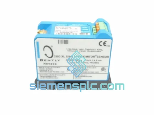
Bently Nevada 330180-52-05 Proximity Transducer
3301
Origin US
Proximity Transducer
Bently Nevada
RFQ Ready
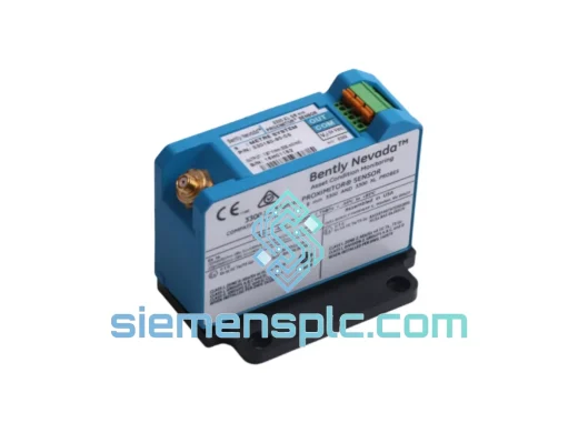
Bently Nevada 330180-51-05 Proximitor Sensor
3301
Origin US
Vibration Sensor
Bently Nevada
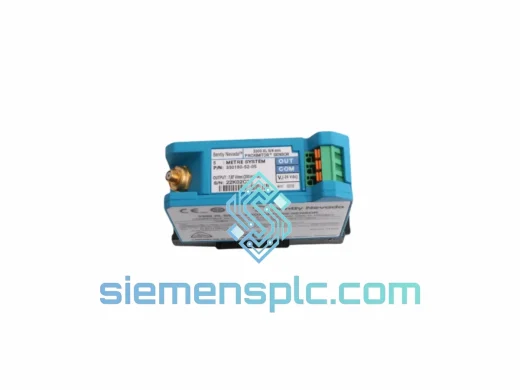
RFQ Ready
Bently Nevada 330180-51-00 Proximitor Sensor
3301
Origin US
Vibration Monitoring Sensor