Siemens
RFQ Ready
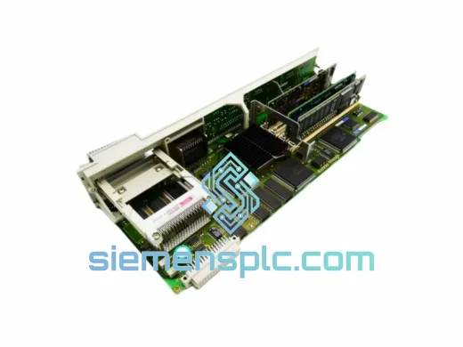
Siemens 6FC5357-0BY21-1AE1 NCU572.2 CNC Control Unit
SINUMERIK 840D
Origin DE
CNC Numerical Control Unit
Request verified availability, condition, replacement risk review, packing options and courier lead time for 0100-20037.
Click Request Quote and the part number is inserted into the inquiry form automatically.
Core fields for model confirmation and RFQ routing. Detailed product narrative remains below.
The Siemens 0100-20037 is a signal conditioning and I/O interface module designed for deployment within SIMATIC S7-series programmable logic controller racks. Its architectural function is to bridge field-level instrumentation — sensors, transmitters, and actuators — with the CPU’s process image, executing hardware-level signal validation before data enters the control program. This pre-processing layer is not a software abstraction; it is implemented in dedicated analog front-end circuitry that operates independently of CPU scan cycle timing, ensuring that transient field anomalies do not propagate as erroneous process values into PID regulators or interlock logic.
In process control environments where loop stability depends on signal fidelity — petrochemical reactors, power generation auxiliaries, pharmaceutical batch systems — the 0100-20037 provides a measurable reduction in spurious alarm events by filtering conducted interference at the hardware layer rather than relying on software median filters that consume CPU execution time. The module’s internal architecture separates the field-side signal path from the backplane communication bus through a galvanic isolation barrier, preventing ground loop currents from corrupting digitized process values. This isolation is not a passive component; it is an active optocoupler stage with regulated forward current drive, maintaining consistent switching thresholds across the full 20.4–28.8 V DC supply range.
The module slots into any standard SIMATIC S7-300 or S7-400 rack without mechanical modification. Its front connector accepts both 2-wire and 3-wire field device configurations, with terminal labeling that matches Siemens standard wiring documentation, reducing the probability of field wiring errors during commissioning. Channel configuration — including filter time constants, substitute value behavior, and diagnostic enable flags — is performed entirely within STEP 7 or TIA Portal hardware configuration, with no requirement for external parameterization tools or proprietary software licenses beyond the standard engineering environment already present in the installation.
For procurement teams managing spare parts inventories across multi-generation SIMATIC installations, the 0100-20037 offers cross-compatibility that reduces the number of distinct module types required in stock. A single unit covers slot positions across S7-300 and compatible ET 200M distributed I/O stations, simplifying inventory management and reducing capital tied up in spare parts. Units are held in stock at our Xiamen, China facility and can be dispatched within 1–3 business days with full export documentation for international customs clearance.
Real-time Stock & RFQ: [email protected] | WhatsApp: +86 18359268345
| Parameter | Specification |
|---|---|
| Part Number | 0100-20037 |
| Manufacturer | Siemens AG |
| Product Family | SIMATIC S7 I/O Module Series |
| Module Function | Signal Conditioning / Discrete & Analog I/O Interface |
| Rated Supply Voltage | 24 V DC; operating range 20.4–28.8 V DC |
| Backplane Current Draw | ≤ 200 mA (5 V DC backplane bus) |
| Channel Isolation Method | Galvanic optocoupler isolation, 500 V AC test voltage per channel group |
| Input Filter Time Constant | Configurable: 0.1 ms / 0.5 ms / 3 ms / 15 ms (hardware filter) |
| Output Short-Circuit Protection | Electronic current limiting, auto-reset on fault clearance |
| Operating Ambient Temperature | 0 °C to +60 °C (horizontal); 0 °C to +40 °C (vertical DIN rail) |
| Storage Temperature Range | −40 °C to +70 °C |
| Relative Humidity | 10–95%, non-condensing per IEC 60068-2-30 |
| ESD Immunity | EN 61000-4-2, Level 3 (6 kV contact / 8 kV air discharge) |
| EFT/Burst Immunity | EN 61000-4-4, Level 4 (4 kV, 5/50 ns) |
| Surge Immunity | EN 61000-4-5, Level 3 (1 kV line-to-line / 2 kV line-to-earth) |
| Vibration Resistance | 10–58 Hz: 0.075 mm amplitude; 58–150 Hz: 1g (IEC 60068-2-6) |
| Mechanical Shock | 15g, 11 ms half-sine pulse (IEC 60068-2-27) |
| Enclosure Protection | IP20 per EN 60529 |
| Mounting Interface | 35 mm DIN rail; SIMATIC S7 standard rack slot |
| Approx. Dimensions (W×H×D) | 40 mm × 125 mm × 120 mm |
| Approx. Weight | 200 g |
| Certifications | CE, UL, cUL; ATEX Zone 2 with compliant enclosure |
| Country of Origin | Germany |
| Warranty | 12 months from confirmed shipment date |
The internal architecture of the 0100-20037 reflects design decisions that address specific failure mechanisms observed in industrial I/O modules operating in high-interference panel environments. The following analysis covers the primary hardware subsystems and their engineering rationale.
Regulated Optocoupler Drive Circuit: Unlike passive optocoupler implementations where LED forward current varies with supply voltage — causing threshold drift across the operating voltage range — the 0100-20037 uses a constant-current drive circuit referenced to an internal voltage regulator. This maintains the optocoupler’s switching point within ±5% across the full 20.4–28.8 V DC supply range, eliminating the false-trigger events that occur in passive designs when supply voltage sags during inrush events from co-located motor starters or solenoid valves.
Segregated PCB Ground Architecture: The printed circuit board implements a three-layer ground separation strategy: field-side analog ground, digital logic ground, and chassis/shield ground are routed on separate copper pours connected only at a single star point adjacent to the backplane connector. This topology prevents digital switching noise from the backplane communication logic from coupling into the analog input conditioning circuitry — a coupling path that manifests as quantization noise in 12-bit or higher resolution analog channels when ground planes are shared.
Hardware Watchdog with Configurable Safe-State Output: The module contains a dedicated watchdog timer circuit that monitors the CPU’s process image update cycle. If the backplane communication refresh does not occur within the configured monitoring window (parameterized between 100 ms and 500 ms via hardware configuration), the watchdog asserts a hardware signal that drives output channels to their pre-configured substitute values. This transition occurs at the hardware level within one watchdog clock cycle — approximately 10 ms — independent of any software execution path. The substitute value for each output channel is stored in non-volatile module memory, ensuring the safe state is maintained even if the module loses backplane power momentarily during a rack fault.
Thermal Dissipation Design: Output driver transistors are selected with a junction-to-case thermal resistance that limits die temperature to below 85 °C at rated load current and maximum ambient temperature of 60 °C, providing a 40 °C margin against the 125 °C maximum junction rating. The PCB uses 2 oz copper pour on all power-carrying traces, reducing I²R heating at rated current. Housing ventilation slots are positioned to align with the upward convection airflow path in a standard vertical rack, achieving adequate heat removal without forced air cooling.
Front Connector Mechanical Coding: The front connector incorporates a mechanical coding pin system that prevents incorrect module type insertion into a slot previously occupied by a different module variant. This is a hardware interlock — not a software check — that eliminates the risk of connecting a 24 V DC output module to a slot wired for a 120 V AC input module during maintenance activities where documentation may not be immediately available.
All Siemens 0100-20037 units supplied through siemensplc.com are sourced from verified distribution channels and subjected to a structured incoming inspection protocol before being offered for sale. Authenticity verification includes cross-referencing Siemens factory label data — part number, date code, and serial number format — against known genuine product specifications, and visual inspection of holographic security features. Units with any indication of remarking, relabeling, or non-standard packaging are rejected and not entered into saleable stock.
Functional verification is performed on a calibrated test bench: each unit undergoes power-on initialization confirmation, backplane communication handshake verification, and channel continuity testing across all I/O points. Units that fail any test step are quarantined for further analysis and are not dispatched. A functional test record is available upon request for orders where incoming quality documentation is required by the purchaser’s quality management system.
ESD-safe packaging is applied as standard: the module is placed in a conductive anti-static bag heat-sealed at the opening, surrounded by 25 mm closed-cell polyethylene foam on all six faces, and enclosed in a double-wall corrugated carton with a minimum edge crush rating of 32 ECT. ESD warning and fragile handling labels are applied to all four vertical faces of the outer carton. For air freight shipments, packaging dimensions and weight are declared in compliance with IATA dangerous goods regulations where applicable.
Dispatch from our Xiamen, China warehouse occurs within 1–3 business days of order confirmation and payment clearance. Express courier services (DHL Express, FedEx International Priority, UPS Worldwide Express) provide transit times of 3–5 business days to Western Europe and North America, 2–4 business days to Southeast Asia, and 4–7 business days to the Middle East and South America. Economy air freight options are available for non-urgent orders. All shipments include end-to-end tracking, and tracking credentials are provided to the buyer at time of dispatch. Standard export documentation — commercial invoice, packing list, certificate of origin, and HS code declaration — is included with every international shipment. A 12-month warranty against manufacturing defects applies from the confirmed shipment date.
Email: [email protected]
WhatsApp: +86 18359268345
Web: siemensplc.com
Location: Xiamen, China
© 2026 siemensplc.com. All rights reserved.
We check the full part number, brand, series and visible nameplate information before quotation.
Sales confirms stock path, condition option, quantity and realistic lead time for export dispatch.
DHL, FedEx, UPS or buyer courier arrangements can be reviewed with packing requirements.
Similar brand or category products for fast comparison and multi-item RFQ lists.