TESCH
RFQ Ready
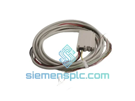
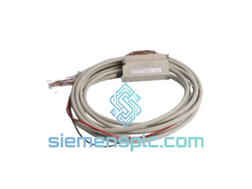
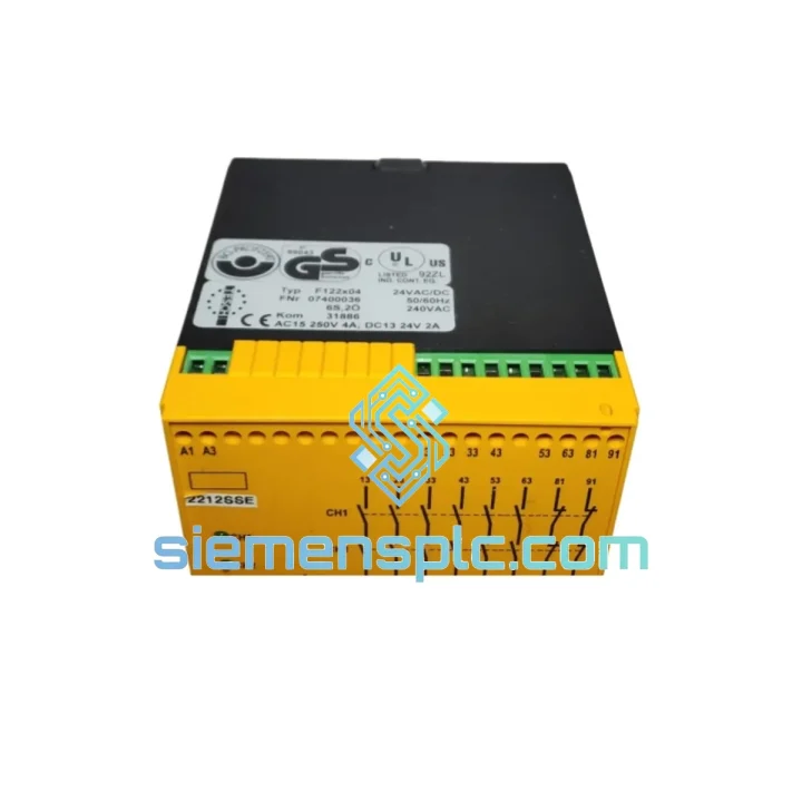
TESCH F121X04 Inductive Proximity Sensor
Origin Not specified
Inductive Proximity Sensor
Request verified availability, condition, replacement risk review, packing options and courier lead time for F12304.
Click Request Quote and the part number is inserted into the inquiry form automatically.
Core fields for model confirmation and RFQ routing. Detailed product narrative remains below.
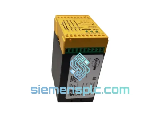
The TESCH F12304 is a hardwired, dual-channel safety relay module purpose-built for emergency stop (E-stop) circuits, interlocked safety gate monitoring, and enabling switch supervision in industrial machinery. Operating within the F-Series product family, the F12304 achieves Performance Level e (PLe) and Category 4 per EN ISO 13849-1:2015, making it one of the highest-rated safety integrity tiers available for electromechanical safety functions. Its architecture is grounded in forced-guided relay technology with cross-circuit detection, ensuring that a single component failure — whether a welded contact, an open-circuit fault, or a wiring short between channels — is detected before the next demand on the safety function.
In a control loop context, the F12304 occupies the logic and output subsystem of a safety function chain. The input subsystem (E-stop button, safety gate switch, or enabling device) feeds two electrically independent channels into the relay’s input terminals. The F12304 evaluates both channels simultaneously: if either channel deviates from its expected state — or if a cross-fault between channels is detected — the module de-energises its safety output contacts and latches in a safe state. This deterministic response, with a measured reaction time of ≤ 20 ms, satisfies the response-time budgets of most Category 4 safety loops without requiring additional timing analysis.
The module supports selectable reset modes. Monitored manual reset requires a deliberate operator action — a momentary closure of the reset input — before the safety outputs re-energise. This prevents automatic restart after an E-stop event, directly satisfying the requirements of ISO 13850 Clause 4.1.4. Automatic reset mode is available for applications where a risk assessment confirms that no hazard exists upon power restoration, such as light curtain re-entry detection in low-risk zones. The reset mode is hardware-selectable via terminal wiring, not firmware, which eliminates the risk of inadvertent mode changes during software updates.
The 22.5 mm DIN rail form factor (EN 60715) allows the F12304 to be integrated into standard control cabinet layouts without dedicated mounting hardware. Snap-fit installation reduces commissioning time, and the screw-terminal wiring interface accommodates conductors from 0.5 mm² to 2.5 mm², covering both signal-grade and power-grade wiring practices. The terminal layout is designed for left-to-right wiring discipline, consistent with IEC 60204-1 panel wiring conventions.
Real-time Stock & RFQ: [email protected] | WhatsApp: +86 18359268345
| Model / SKU | F12304 |
| Brand | TESCH |
| Series | F-Series Safety Relay |
| Function | Dual-channel E-stop & safety gate monitoring |
| Safety Category | Category 4 / PLe (EN ISO 13849-1:2015) |
| SIL Rating | SIL 2 / SIL 3 capable (IEC 62061) |
| Supply Voltage | 24 V DC ±15% |
| Power Consumption | ≤ 3.5 W |
| Safety Output Contacts | 3 × NO (normally open), forced-guided |
| Auxiliary Output | 1 × NC (normally closed), status signalling |
| Output Contact Rating | 6 A / 250 V AC; 6 A / 24 V DC |
| Response Time (de-energise) | ≤ 20 ms |
| Reset Mode | Monitored manual / automatic (terminal-selectable) |
| Input Channel Architecture | Dual-channel, cross-circuit detection |
| Mounting | 22.5 mm DIN rail (EN 60715) |
| Operating Temperature | −10 °C to +55 °C |
| Storage Temperature | −25 °C to +70 °C |
| Protection Class | IP40 (terminal area) |
| Weight | 270 g |
| Certifications | CE, TÜV, EN ISO 13849-1, IEC 62061 |
| Country of Origin | Germany |
| Warranty | 12 months from date of shipment |
The F12304’s internal architecture is built around forced-guided (mechanically linked) relay contacts, a design requirement under EN 50205 Class A. In a forced-guided relay, the NO and NC contacts are mechanically coupled such that they cannot simultaneously occupy the same state. If an NO contact welds closed due to overcurrent or arcing, the mechanical linkage physically prevents the NC contact from opening — and vice versa. This property is the hardware foundation of cross-circuit detection: the F12304 monitors the state of its own output contacts via the NC auxiliary path and compares it against the commanded state. Any discrepancy — indicating a welded or failed contact — blocks re-energisation of the safety outputs on the next reset attempt.
The dual-channel input circuit uses separate, electrically isolated paths for Channel 1 and Channel 2. Each channel drives an independent input relay coil. The F12304’s internal logic requires both input relays to be energised within a defined simultaneity window (typically ≤ 500 ms) before the safety outputs are permitted to close. This simultaneity check prevents a single stuck-at-high fault on one channel from holding the outputs energised while the other channel has de-activated — a failure mode that would otherwise be undetectable in a single-channel architecture.
EMC performance is addressed through suppression diodes across the relay coils, limiting inductive kickback transients to levels compliant with IEC 61000-4-4 (electrical fast transient / burst) and IEC 61000-4-5 (surge). The 24 V DC supply input incorporates reverse-polarity protection, preventing damage from incorrect wiring during commissioning. The compact housing uses a flame-retardant thermoplastic rated UL 94 V-0, providing a degree of arc containment in the event of an internal fault.
The terminal block design uses captive screws with vibration-resistant thread geometry, maintaining contact integrity in environments subject to mechanical vibration up to 10–55 Hz per IEC 60068-2-6. This is particularly relevant in applications mounted on machine frames rather than isolated control cabinets.
Every TESCH F12304 unit supplied by siemensplc.com is sourced through verified industrial distribution channels and subjected to incoming inspection prior to dispatch. Inspection procedures include label authenticity verification, housing integrity assessment, date-code and batch traceability cross-referencing, and functional continuity testing across all output contacts. Units are stored in anti-static, climate-controlled conditions to preserve contact surface integrity and relay coil insulation resistance.
Shipments originate from our warehouse in Xiamen, China. Xiamen’s port infrastructure supports both express courier (DHL, FedEx, UPS) and consolidated air freight, with typical transit times of 3–7 business days to major industrial hubs in Southeast Asia, the Middle East, Europe, and North America. Export documentation — including commercial invoice, packing list, and certificate of origin — is prepared to customs standards for smooth clearance. For time-critical procurement, same-day dispatch is available for in-stock units when orders are confirmed before 14:00 CST.
All units carry a 12-month warranty from the date of shipment, covering manufacturing defects and contact failure under normal operating conditions. Warranty claims are processed with a target response time of 48 hours. Replacement units are dispatched via express courier at no additional freight cost for confirmed warranty cases.
Email: [email protected]
WhatsApp: +86 18359268345
Web: siemensplc.com
Location: Xiamen, China
© 2026 siemensplc.com. All rights reserved.
We check the full part number, brand, series and visible nameplate information before quotation.
Sales confirms stock path, condition option, quantity and realistic lead time for export dispatch.
DHL, FedEx, UPS or buyer courier arrangements can be reviewed with packing requirements.
Similar brand or category products for fast comparison and multi-item RFQ lists.