AMCI
RFQ Ready
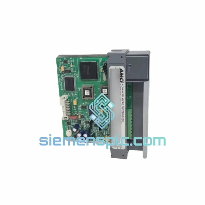
AMCI 7264 Motion Interface Module – 7000 Series
7000 Series
Origin United States
Motion Control Module
Request verified availability, condition, replacement risk review, packing options and courier lead time for AMCI-1531.
Click Request Quote and the part number is inserted into the inquiry form automatically.
Core fields for model confirmation and RFQ routing. Detailed product narrative remains below.
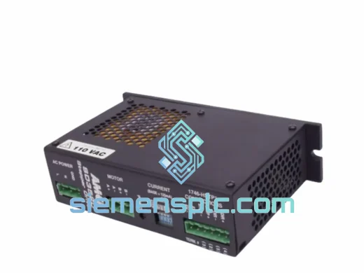
The AMCI 1531 occupies a single I/O slot in any Allen-Bradley SLC 500 rack and performs one tightly scoped function: it excites a brushless resolver with a precision sine-wave carrier, demodulates the returned sin/cos signals through a dedicated resolver-to-digital converter (RDC) ASIC, and presents a 16-bit absolute position word plus a velocity register directly to the SLC 500 processor via the backplane data highway. No external signal conditioner, no gateway, no additional power supply rail beyond the standard 5 VDC and 24 VDC backplane feeds. The module eliminates the analog wiring runs and noise susceptibility that accompany traditional tachometer or encoder feedback schemes, replacing them with a fully digital, deterministic data path that the processor reads on every scan cycle.
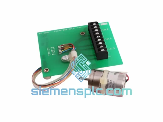
In a closed-loop position or velocity control architecture, the 1531 sits between the resolver mounted on the motor shaft and the SLC 500 CPU. The CPU writes configuration parameters — excitation frequency, velocity filter time constant, fault thresholds — to the module’s output image table during initialization. From that point forward, the module operates autonomously: it generates the excitation signal, tracks shaft angle through the RDC tracking loop, computes velocity by differentiating successive position samples over a fixed time base, and updates the input image table every backplane scan. The CPU reads position and velocity data with standard ladder rung instructions, exactly as it would read any analog input module, which means no custom function blocks or motion-specific firmware are required on the processor side.
Real-time Stock & RFQ: [email protected] | WhatsApp: +86 18359268345
| Manufacturer | AMCI (Advanced Micro Controls Inc.) |
| Part Number / SKU | AMCI-1531 |
| Module Category | Resolver Interface Module |
| Product Series | AMCI 1500 Series |
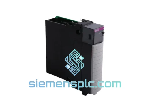
| Backplane Compatibility | Allen-Bradley SLC 500 (all rack sizes: 4-, 7-, 10-, 13-slot) |
| Slot Consumption | 1 single I/O slot |
| Resolver Excitation Output | Sine-wave, 2 Vrms ± 2%, frequency selectable (typically 2.5 kHz or 5 kHz) |
| Resolver Transformation Ratio | 0.5 (standard single-speed brushless resolver) |
| Position Resolution | 16-bit absolute (65,536 counts per revolution) |
| Position Accuracy | ±1 LSB under steady-state conditions |
| Velocity Output | Computed from position differential; 16-bit signed integer, units configurable |
| Input Channels | 1 (single-axis) |
| Backplane Power Draw | 5 VDC @ 250 mA (logic); 24 VDC @ 100 mA (field side) |
| Operating Temperature | 0 °C to +60 °C |
| Storage Temperature | -40 °C to +85 °C |
| Relative Humidity | 5% to 95% non-condensing |
| Vibration Rating | IEC 68-2-6: 2 g, 10–500 Hz |
| Shock Rating | IEC 68-2-27: 30 g, 11 ms half-sine |
| Certifications | UL Listed, CE Marked (EMC Directive) |
| Warranty | 12 months from date of shipment (siemensplc.com) |
The signal chain inside the 1531 begins at the excitation amplifier. A crystal-controlled oscillator generates the carrier frequency reference; a precision DAC and low-distortion amplifier produce the resolver excitation sine wave with total harmonic distortion below 0.5%, which is a prerequisite for achieving the module’s rated angular accuracy. Low-distortion excitation is not a cosmetic specification — harmonic content in the excitation signal folds back into the demodulated position data as a periodic angular error that cannot be filtered without also degrading dynamic response.
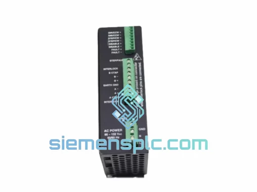
The returned sin and cos signals from the resolver pass through differential input receivers with common-mode rejection ratios exceeding 60 dB. This level of CMRR is the primary defense against ground-loop noise on long cable runs between the module and the resolver, which in practice can span 30 meters or more in large machine frames. After the differential receivers, synchronous demodulators strip the carrier frequency, leaving baseband sin(θ) and cos(θ) signals proportional to shaft angle θ. These feed the RDC tracking loop, which is a second-order phase-locked loop implemented in the ASIC. The tracking loop continuously drives its internal angle estimate toward the true shaft angle; the loop bandwidth is set conservatively to reject high-frequency mechanical vibration while maintaining adequate dynamic tracking at the maximum rated shaft velocity.
The 16-bit position word produced by the RDC is latched into a dual-port RAM buffer on the module’s local bus. The SLC 500 backplane interface logic reads this buffer and transfers the data to the processor’s input image table during the normal I/O scan. Because the latch and transfer are synchronized to the backplane scan, the position data presented to the CPU is always coherent — there is no risk of reading a partially updated word that spans two consecutive RDC output cycles.
EMC hardening on the 1531 follows a layered approach. The PCB uses a four-layer stackup with dedicated ground and power planes to minimize loop areas for high-frequency return currents. Ferrite beads on the resolver cable interface pins attenuate common-mode RF energy conducted in from the field wiring. The module’s metal faceplate bonds directly to the SLC 500 rack’s chassis ground rail, providing a low-impedance path for shield termination and ensuring the module participates in the rack’s overall Faraday enclosure.
Every AMCI 1531 unit dispatched from our Xiamen, China facility undergoes a structured incoming inspection protocol before it enters bonded stock. Inspection covers label and date-code verification against AMCI’s published part number matrix, visual examination of the PCB and connector contacts under magnification, and a powered functional test on an SLC 500 rack that confirms backplane communication, excitation output amplitude and frequency, and position data integrity across a full 360-degree resolver rotation. Units that do not pass all test criteria are quarantined and returned to the supply chain — they do not enter saleable stock.
Packaging follows anti-static handling standards: each module is placed in a conductive foam tray inside an ESD shielding bag, sealed with a humidity indicator card, and boxed with sufficient void fill to withstand the shock and vibration levels specified in ISTA 2A transit testing. For international shipments, we work with DHL Express, FedEx International Priority, and UPS Worldwide Express, with typical transit times of 3–5 business days to Europe and North America. Export documentation — commercial invoice, packing list, and certificate of origin — is prepared to the importing country’s customs requirements. HS code 8537.10 applies to this product category for most jurisdictions. All units shipped from siemensplc.com carry a 12-month warranty covering manufacturing defects and functional failure under normal operating conditions.
Email: [email protected]
WhatsApp: +86 18359268345
Web: siemensplc.com
Location: Xiamen, China
© 2026 siemensplc.com. All rights reserved.
We check the full part number, brand, series and visible nameplate information before quotation.
Sales confirms stock path, condition option, quantity and realistic lead time for export dispatch.
DHL, FedEx, UPS or buyer courier arrangements can be reviewed with packing requirements.
Similar brand or category products for fast comparison and multi-item RFQ lists.