GE
In Stock OK
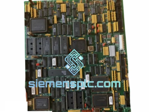
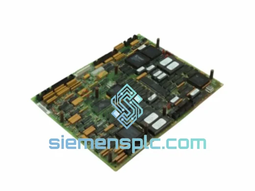
GE DS200SDCCG5AHD Drive Control Board – Mark V Series
Request verified availability, condition, replacement risk review, packing options and courier lead time for DS200SDCCG5AHD.
BrandGE
Part NumberDS200SDCCG5AHD
ConditionAvailability Check
Lead TimeRFQ Confirmation
DocumentsDatasheet / photos by RFQ
ShippingExport packing available
Auto-filled RFQ
DS200SDCCG5AHD
Click Request Quote and the part number is inserted into the inquiry form automatically.
- Reply by email: [email protected]
- WhatsApp / Tel: +86 18359268345
- Mon-Sat 9:00-18:00 GMT+8
Procurement Data
Key Product Information
Core fields for model confirmation and RFQ routing. Detailed product narrative remains below.
- Brand
- GE
- Primary Part Number
- DS200SDCCG5AHD
- Product Type
- Drive Control Board
- Series / Family
- Mark V
- Manufacturer
- General Electric (GE)
- Country of Origin
- US
- Catalog Category
- Motor Drives
- Operating Temp.
- 0°C to +60°C panel ambient
- Warranty
- 12 months from shipment date against manufacturing defects and functional failure
Model confirmed for inquiry
DS200SDCCG5AHD
Send quantity, destination and urgency. The RFQ form keeps this part number attached.
Request Quote
Product Overview
DS200SDCCG5AHD — Speed Governor Analog Output Conditioning Card in the GE Mark V Distributed Turbine Control Architecture
The DS200SDCCG5AHD is the fifth-generation Speed/Drive Control Card (SDCC) deployed within GE’s Mark V turbine control platform. Its operational boundary is precisely defined: it receives a digital drive demand word from the Mark V TCCA or TCCB processor boards via the proprietary backplane bus, applies the final stage of closed-loop PID correction, and delivers a conditioned analog output — selectable between 4–20 mA and ±10 V DC — to the downstream static excitation system or variable-frequency drive. This board occupies the interface between the digital control domain and the analog power electronics domain. Signal integrity at this boundary determines the accuracy of the turbine’s speed governor loop under all operating conditions, including load transients, grid frequency deviations, and partial-load steady-state operation.
In a Mark V TMR (Triple Modular Redundancy) configuration, three TCCA processors independently compute drive demand values. The Mark V voting logic arbitrates these values before passing the consensus result to the DS200SDCCG5AHD. The board therefore operates exclusively on a voted, fault-tolerant command — it does not perform inter-processor arbitration. Its function is faithful, low-latency conversion of that arbitrated command into a calibrated analog signal. Gain error, offset drift, or output nonlinearity in the DS200SDCCG5AHD translates directly into a speed reference error at the drive, with consequences ranging from load oscillation to turbine trip on overspeed protection.
The G5 hardware revision addresses semiconductor component obsolescence in earlier SDCC generations. GE’s component substitution process for this revision required full electrical characterization of replacement devices against original specifications, followed by system-level validation in a Mark V test rig. The AHD configuration suffix identifies the specific output range and interface variant. This suffix must be matched against the plant’s Mark V panel documentation before procurement — substituting an incorrect AHD variant produces output scaling errors that are not detectable during bench testing but manifest as governor instability under load.
The DS200SDCCG5AHD is in active service across gas turbine generators, steam turbine control panels, large compressor trains, and motor drive systems in power generation, LNG, petrochemical, and heavy industrial facilities worldwide. The Mark V platform, despite GE’s transition to Mark VIe, remains operational at thousands of installations globally. The DS200SDCCG5AHD is a non-interchangeable, board-specific replacement with no cross-compatible substitute within the Mark V I/O tier. Operators managing Mark V assets through extended service life — typically 10–15 years beyond GE’s original support window — require verified, genuine spare boards to sustain operations without unplanned downtime.
Real-time Stock & RFQ: [email protected] | WhatsApp: +86 18359268345
Technical Parameters
| Parameter | Specification |
|---|---|
| Part Number | DS200SDCCG5AHD |
| Manufacturer | General Electric (GE) |
| Series / Platform | Mark V Turbine Control System |
| Board Function | Speed/Drive Control Card — analog drive demand output conditioning |
| Hardware Revision | G5 — component-obsolescence update, full backward compatibility |
| Configuration Variant | AHD — must be verified against plant Mark V panel revision documentation |
| Analog Output Modes | 4–20 mA current loop or ±10 V DC voltage (configuration-file selected, no hardware modification) |
| Output Resolution | 12-bit DAC minimum; output accuracy ±0.1% of full scale at 25°C |
| Backplane Interface | Mark V proprietary VME-derivative parallel bus; 5 VDC logic levels |
| Supply Voltages | +5 VDC (logic), ±15 VDC (analog stage) — sourced from Mark V power distribution board |
| Control Frame Update Rate | 10 ms or 20 ms (application-configured); output updated synchronously each frame |
| Operating Temperature | 0°C to +60°C panel ambient |
| Storage Temperature | −25°C to +70°C |
| Relative Humidity | 5% to 95% RH, non-condensing |
| EMC Immunity | IEC 61000-4-2 (ESD), IEC 61000-4-4 (EFT), IEC 61000-4-5 (surge) — industrial environment ratings |
| Watchdog Timer | Hardware watchdog, independent oscillator; configurable timeout 100–500 ms; output clamped to zero on assertion |
| Fault Output Behavior | Analog output hardware-clamped to zero demand on watchdog assertion, power fault, or self-test failure — firmware-independent |
| Diagnostic Interface | Board status register polled by TCCA via backplane each control frame; fault codes logged in Mark V historian with frame-level timestamp |
| Form Factor | PCB module, Mark V rack-mount format; direct slot installation, no adapter hardware |
| Country of Origin | United States of America |
| Warranty | 12 months from shipment date against manufacturing defects and functional failure |
Hardware Logical Analysis
The DS200SDCCG5AHD signal chain begins at the backplane bus interface, where the board latches the drive demand word — a 12-bit or 16-bit integer representing the percentage of full-scale drive output commanded by the Mark V speed governor algorithm — at the start of each control frame. A precision DAC converts the latched value to an analog voltage. An output buffer amplifier stage then conditions this voltage to drive the load impedance of the downstream electronics over cable runs that, in large turbine enclosures, can exceed 15 meters. An unbuffered DAC output at these distances would exhibit load-dependent voltage errors that exceed the governor’s allowable speed reference tolerance; the buffer stage eliminates this error source by presenting a low output impedance independent of cable and load characteristics.
The PCB layout enforces a physical partition between the analog signal section and the digital logic section through a ground plane split and a component placement boundary. Digital switching currents — which generate broadband noise from DC to several MHz at Mark V bus operating frequencies — are confined to the digital ground plane. This prevents capacitive and inductive coupling of switching noise into the analog ground reference used by the DAC and output amplifier. Without this partition, digital switching noise would appear as a superimposed AC component on the drive demand output, manifesting as speed reference jitter at the drive and, in sensitive governor loops, as low-amplitude speed oscillation at the turbine shaft under steady-state conditions.
Discrete I/O lines — fault status outputs and drive enable inputs — are routed through optocoupler isolation stages. The optocouplers provide galvanic separation between the Mark V panel’s internal logic ground and the external drive system’s signal ground. In installations where the drive electronics are housed in a separate panel with an independent ground reference, ground potential differences between panel sections introduce DC offset currents into signal conductors. Without isolation, these currents appear as DC offset errors on the analog output. The optocoupler stages eliminate this error mechanism entirely, maintaining output accuracy independent of the installation’s grounding topology.
The hardware watchdog circuit operates from a dedicated oscillator that is independent of the board’s main clock and firmware execution environment. The firmware loop must write a specific bit pattern to the watchdog service register within the configured timeout window. A firmware hang, stack overflow, or processor fault that prevents this write causes the watchdog to assert a hardware reset signal and simultaneously set a fault latch bit in the board’s status register. A hardware clamp circuit connected to the watchdog assertion line pulls the analog output to zero volts regardless of the DAC register contents. This architecture ensures that a firmware failure cannot produce a frozen, non-zero drive demand — a condition that would cause uncontrolled turbine acceleration if the drive electronics remained enabled during a control board fault.
The G5 revision replaces end-of-life analog switch ICs and precision voltage reference devices from the original SDCC design with components that remain in active semiconductor production. GE’s substitution validation process required full electrical characterization of each replacement component against the original device’s datasheet parameters, followed by system-level testing in a Mark V test rig across the full operating temperature range. The result is a board that presents an identical electrical interface to the Mark V system while using components with confirmed long-term supply availability — a material consideration for operators managing Mark V assets through extended service life.
System Integration Benefits
- Direct rack installation without modification: The DS200SDCCG5AHD installs into the Mark V rack slot without adapter hardware, firmware patches, or reconfiguration of TCCA/TCCB processor boards. Replacement is a board-swap followed by the standard Mark V diagnostic reset sequence — no application software changes are required, and the control system resumes normal operation within the first post-swap control frame.
- Control-frame-synchronous output update: The analog output is updated at the Mark V control frame rate — 10 ms or 20 ms depending on application configuration. Drive demand corrections computed by the speed governor algorithm are applied within a single frame, preserving the closed-loop bandwidth required for stable speed control during load transients and grid frequency disturbances.
- Frame-level fault timestamping in the Mark V historian: Board health status is reported to the TCCA processor via the backplane status bus at every control frame. Fault events are logged in the Mark V event historian with frame-level timestamp resolution, enabling post-trip analysis without external data acquisition hardware or manual fault correlation across separate logging systems.
- Firmware-independent safe-state output enforcement: On any detected board fault — watchdog timeout, power supply undervoltage, or self-test failure — the analog output is clamped to zero demand by a hardware circuit that operates independently of firmware state. This behavior is deterministic and cannot be masked by a concurrent firmware fault, ensuring that a board failure does not produce an uncontrolled drive excitation condition.
- Galvanic isolation of drive signal ground: Optocoupler isolation on discrete I/O lines eliminates ground loop interference between the Mark V panel and the drive electronics enclosure. This isolation maintains analog output accuracy in installations with significant ground potential differences between panel sections — a common condition in large industrial facilities with distributed grounding systems and multiple independent ground references.
- TMR voting architecture compatibility: In TMR-configured Mark V systems, the DS200SDCCG5AHD receives the arbitrated, voted drive demand value from the Mark V voting logic. A single TCCA processor fault does not propagate to the drive output; the voted value remains valid as long as two of three processors agree. The board faithfully converts that consensus value to an analog signal without participating in the arbitration process.
- Dual output mode without hardware modification: The board supports both 4–20 mA current loop and ±10 V DC voltage output modes, selectable through the Mark V application configuration file. This accommodates drive electronics from multiple manufacturers and allows the same board type to serve different turbine applications within a plant’s fleet without maintaining separate spare part inventories for each output mode.
- Extended Mark V fleet operability: Operators routinely defer migration from Mark V to Mark VIe by 10–15 years due to capital cost and outage scheduling constraints. Maintaining a verified supply of genuine DS200SDCCG5AHD boards is a prerequisite for sustaining these assets through their operational life. A single unplanned turbine trip caused by an unavailable spare board carries a cost that exceeds the value of an entire spare board inventory by an order of magnitude in most power generation and process industry applications.
Quality Assurance & Global Logistics
Each DS200SDCCG5AHD unit supplied through siemensplc.com undergoes a structured pre-shipment verification protocol before dispatch. Visual inspection examines the PCB surface, component seating, solder joint integrity, and edge connector pin condition — failure modes prevalent in boards recovered from decommissioned panels or stored without ESD protection. Functional bench testing applies the correct supply voltages (+5 VDC, ±15 VDC), exercises the analog output across the full demand range (0% to 100% in 10% increments), verifies watchdog operation by inducing a timeout and confirming hardware output clamp behavior, and checks backplane bus communication signaling. Units that do not satisfy all functional test criteria are quarantined and not offered for sale.
Packaging follows IPC/JEDEC J-STD-033 ESD handling guidelines: boards are sealed in anti-static shielding bags, cushioned in conductive foam, and placed in rigid corrugated cartons with a minimum 50 mm foam liner on all faces. Each shipment includes a functional test record, a condition declaration (new OEM or tested-functional, as applicable), and a commercial invoice prepared to the import documentation requirements of the destination country, including HS code classification for customs clearance.
Export logistics from Xiamen, China are managed through established partnerships with DHL Express, FedEx International Priority, and air freight consolidators. Standard transit times are 3–5 business days to Southeast Asia and Northeast Asia, 5–7 business days to the Middle East, Europe, and Australia, and 5–8 business days to North and South America. For confirmed in-stock orders received before 14:00 CST, same-day dispatch is available. The 12-month warranty is processed on a replacement-first basis: a replacement unit is dispatched upon receipt of the failed board, minimizing plant downtime. Engineering support for Mark V configuration questions, compatibility verification, and integration guidance is available throughout the warranty period and beyond at no additional charge.
Contact Information
Email: [email protected]
WhatsApp: +86 18359268345
Web: siemensplc.com
Location: Xiamen, China
© 2026 siemensplc.com. All rights reserved.
Ready to quote
[email protected]
Send This Part Number to Sales
RFQ workflow
Quality workflow ->
Confirmation Process
01Model confirmation
We check the full part number, brand, series and visible nameplate information before quotation.
02Availability reply
Sales confirms stock path, condition option, quantity and realistic lead time for export dispatch.
03Packing & courier
DHL, FedEx, UPS or buyer courier arrangements can be reviewed with packing requirements.
Continue sourcing
Browse full catalog ->
Related Automation Parts
Similar brand or category products for fast comparison and multi-item RFQ lists.
GE
RFQ Ready
GE DS200TCQCG1RJD Drive Control Board – Mark V EX2100
Mark V
Origin US
Drive Control Board
GE
RFQ Ready
GE DS200SDCCG5RHD Drive Control Board – Mark V Speedtronic
Mark V
Origin US
Drive Control Board