GE Multilin
RFQ Ready
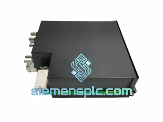
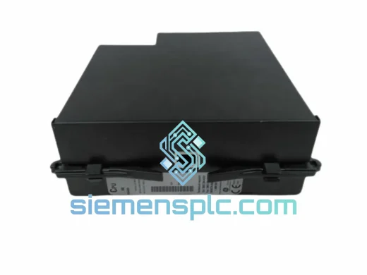
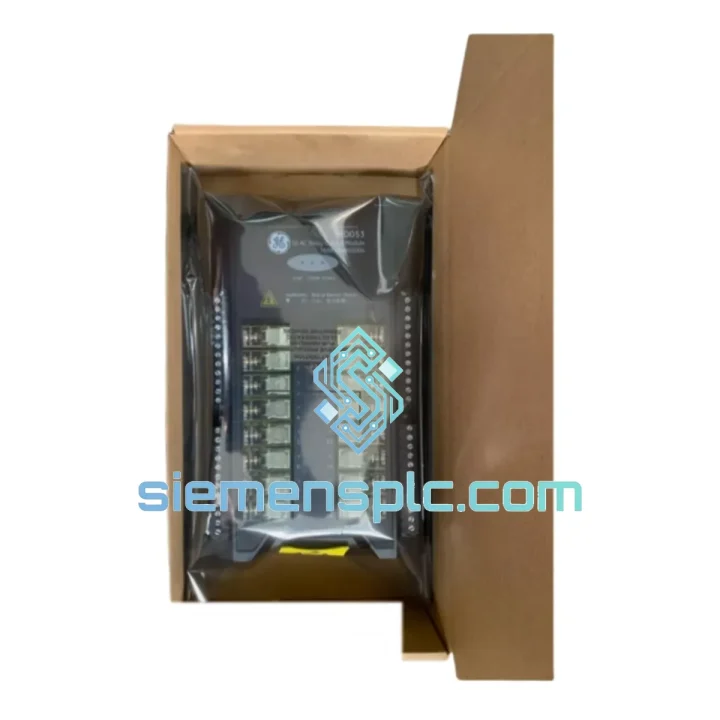
GE Multilin UR8AH Protection Relay Module
UR Series
Origin US
Protection Relay Module
Request verified availability, condition, replacement risk review, packing options and courier lead time for MAI22-369B1841G5004.
Click Request Quote and the part number is inserted into the inquiry form automatically.
Core fields for model confirmation and RFQ routing. Detailed product narrative remains below.
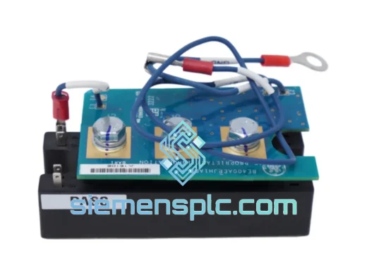
The GE Multilin MAI22-369B1841G5004 is a full-featured motor management relay belonging to the 369 Motor Management Relay platform — a purpose-built protection and monitoring device for medium-voltage motors and generators operating in demanding industrial environments. Unlike generic overcurrent relays, the 369 series integrates thermal model computation, multi-function ANSI protection elements, and serial communication into a single 4U panel-mount chassis, reducing panel footprint while consolidating protection logic that would otherwise require three to five discrete relays.
In a typical motor control loop, this relay sits between the current transformer (CT) secondary circuits and the motor contactor or circuit breaker trip coil. It continuously samples three-phase current waveforms at high resolution, applies configurable ANSI protection curves, and issues trip or alarm outputs within the response time dictated by the selected time-overcurrent characteristic. The thermal model tracks motor heating across start cycles, running load, and stall conditions — a capability that is architecturally distinct from simple I²t integration and accounts for ambient temperature derating and cooling time constants.
The MAI22 hardware variant within the 369 family denotes a specific I/O and power supply configuration. The G5004 suffix identifies the firmware and feature set loaded at the factory, which includes the full complement of protection functions listed below. This part number is traceable to GE Multilin’s manufacturing records and carries the associated factory calibration data.
Real-time Stock & RFQ: [email protected] | WhatsApp: +86 18359268345
| Parameter | Specification |
|---|---|
| Manufacturer | GE Multilin (General Electric) |
| Full Part Number | MAI22-369B1841G5004 |
| Series | Multilin 369 Motor Management Relay |
| Hardware Variant | MAI22 (analog I/O module configuration) |
| Firmware / Feature Set | G5004 |
| CT Input Rating | 1 A or 5 A secondary (field-selectable) |
| Auxiliary Power Supply | 110–240 V AC / 88–300 V DC (wide-range input) |
| Frequency | 50 / 60 Hz |
| Phase Current Measurement Accuracy | ±0.5% of full scale |
| Ground Fault CT Input | Dedicated 50:0.025 A core-balance CT input |
| Protection Functions (ANSI) | 49 Thermal Overload, 50/51 Phase Overcurrent, 50N/51N Ground Fault, 46 Phase Unbalance, 37 Undercurrent, 87 Differential (optional), 27/59 Under/Overvoltage (with VT input) |
| Output Relays | 4 × Form-C electromechanical, 250 V AC / 8 A rated |
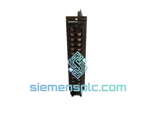
| Digital Inputs | 8 × optically isolated, 24–250 V DC/AC |
| Communication Port | RS-485, Modbus RTU protocol |
| Baud Rate | 1,200 – 19,200 bps (configurable) |
| Front Panel Interface | 2 × 20 character LCD, LED status indicators, keypad |
| Mounting | Panel flush-mount, 4U rack; cutout 177 × 177 mm |
| Operating Temperature | −20 °C to +60 °C |
| Storage Temperature | −40 °C to +85 °C |
| Relative Humidity | 5% – 95% non-condensing |
| Dielectric Withstand | 2,000 V AC for 1 minute (IEC 60255-5) |
| EMC Compliance | IEC 61000-4-2/3/4/5/6, CE marked |
| Weight | Approx. 6.5 kg |
| Country of Origin | USA / Canada |
| Warranty | 12 months from date of shipment |
The 369 relay’s signal chain begins at the CT input terminals, where burden resistors are sized to maintain CT accuracy across the full measurement range. The analog front-end uses a dedicated sigma-delta ADC per phase channel, sampling at a rate sufficient to resolve the 5th harmonic — relevant for motors fed by variable-frequency drives (VFDs) where harmonic distortion can cause false thermal model accumulation if not properly filtered. The DSP core applies a discrete Fourier transform (DFT) to extract fundamental-frequency phasors, which feed both the metering registers and the protection element comparators simultaneously, eliminating the latency that would exist in a sequential processing architecture.
The thermal model implemented in the G5004 firmware is a dual-time-constant algorithm. It maintains separate heating and cooling time constants (τ_heat, τ_cool), both configurable to match the motor’s thermal class per IEC 60034-11. The model accumulates thermal capacity used (TCU) as a percentage, and the relay issues an alarm at a user-defined TCU threshold (typically 90%) before the trip threshold (100%). This staged response allows operators to shed load or initiate a controlled shutdown rather than experiencing an abrupt trip.
The output relay drivers are galvanically isolated from the measurement circuits via optocouplers on the digital input side and relay coil drivers on the output side. The trip output relay is configured as normally energized (fail-safe) by default, meaning a loss of auxiliary power causes the relay to de-energize and issue a trip signal — a design choice that prevents undetected relay failure from leaving a motor unprotected. The RS-485 transceiver is protected against ±15 kV ESD transients per IEC 61000-4-2 Level 4, and the communication circuit is isolated from the measurement ground plane to prevent ground loop interference in multi-drop bus topologies.
The front-panel keypad and LCD operate on a separate microcontroller that communicates with the main protection processor via an internal SPI bus. This architecture ensures that a front-panel lockup or display fault does not affect protection function execution — a critical design separation for safety-rated applications.
Every GE Multilin MAI22-369B1841G5004 unit supplied by siemensplc.com is sourced through verified channels with full traceability to GE Multilin’s manufacturing and calibration records. Units are inspected upon receipt for physical integrity, label authenticity, and firmware version consistency with the G5004 specification. Where factory test reports are available, these are provided to the buyer upon request.
Shipments originate from our warehouse in Xiamen, China — a major export hub with direct access to international freight forwarders and express courier networks including DHL, FedEx, and UPS. Standard export documentation (commercial invoice, packing list, certificate of origin) is prepared for every shipment. For orders requiring customs clearance support, HS code classification assistance and export license coordination are available. Typical dispatch time after order confirmation is 1–3 business days for in-stock units. Air freight transit to major destinations in Europe, Southeast Asia, the Middle East, and the Americas is typically 3–7 business days.
All units are shipped in anti-static packaging with foam cushioning rated for the relay’s weight class. A 12-month warranty covers manufacturing defects and functional failures under normal operating conditions. Warranty claims are processed with a replacement-first policy to minimize downtime for the end user.
📧 Email: [email protected]
💬 WhatsApp: +86 18359268345
🌐 Web: siemensplc.com
📍 Location: Xiamen, China
© 2026 siemensplc.com. All rights reserved.
We check the full part number, brand, series and visible nameplate information before quotation.
Sales confirms stock path, condition option, quantity and realistic lead time for export dispatch.
DHL, FedEx, UPS or buyer courier arrangements can be reviewed with packing requirements.
Similar brand or category products for fast comparison and multi-item RFQ lists.