ALSTOM
RFQ Ready
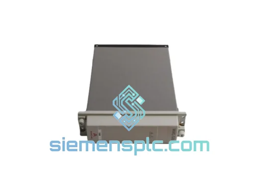
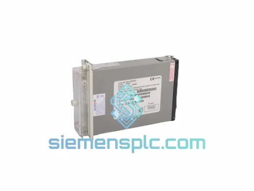
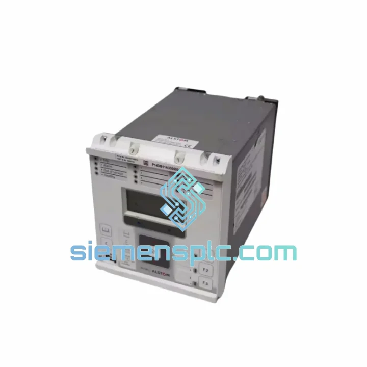
ALSTOM MMLG01 Relay Test Block
MMLG Series
Origin United Kingdom (ALSTOM Grid manufacturing)
Relay Test Block
Request verified availability, condition, replacement risk review, packing options and courier lead time for P14DB11A330500A.
Click Request Quote and the part number is inserted into the inquiry form automatically.
Core fields for model confirmation and RFQ routing. Detailed product narrative remains below.
Every minute a 110 kV feeder sits dead costs real money — lost generation, contractual penalties, regulator scrutiny. The MiCOM P14DB11A330500A is on the shelf in Xiamen right now. We have processed enough emergency relay replacements to know that the difference between a 6-hour outage and a 3-day outage is almost always logistics, not engineering. We handle the logistics. You handle the commissioning.
URGENT REQUIREMENT? Contact: [email protected] | WhatsApp: +86 18359268345
| Parameter | Specification | Status |
|---|---|---|
| Part Number | P14DB11A330500A | ✔ Ready to Ship |
| Manufacturer | ALSTOM Grid (GE Grid Solutions) | |
| Platform | MiCOM P14D | |
| Protection Function | Numerical Distance (21 / 21N), up to 5 forward + 1 reverse zones | |
| Impedance Characteristic | Quadrilateral & Mho (selectable per zone) | |
| VT Input (rated) | 100 / 110 / 120 V AC (phase-to-phase) | |
| CT Input (rated) | 1 A or 5 A nominal | |
| Auxiliary Supply | 24–250 V DC / 100–240 V AC (wide-range SMPS) | |
| Frequency | 50 / 60 Hz | |
| Zone 1 Trip Time | < 20 ms (typical) | |
| Fault Location Accuracy | ±1% of line length | |
| Binary Inputs | 8 optically isolated | |
| Output Contacts | 7 configurable relay outputs | |
| Communication | RS485 rear port; IEC 60870-5-103 / MODBUS RTU; optional IEC 61850 GOOSE | |
| Disturbance Recorder | 8 analogue + 16 digital channels, 1 kHz sampling | |
| Mounting | 19-inch rack, 4U | |
| Dimensions (H×W×D) | 177 × 483 × 225 mm | |
| Operating Temperature | −10 °C to +55 °C | |
| Ingress Protection | IP52 (front panel) | |
| Standards | IEC 60255, IEC 61000 (EMC), EN 50263 | |
| Weight (shipped) | ~19 kg | |
| Origin | France (ALSTOM Grid) |
Before you pull the old unit:
Back up the settings file using MiCOM S1 Studio before de-energizing. Connect via the front RS232 port, navigate to File → Save Settings, and record the firmware version displayed in the relay header. This version string determines whether your saved .set file will load cleanly into the replacement unit without a schema mismatch error.
Firmware matching — the step most engineers skip:
The P14D platform has gone through several firmware generations. A settings file from a v30 relay will not load into a v43 relay without conversion. Check the label on the rear of the unit for the software reference (e.g., P14Dv030F00). If the replacement unit carries a different firmware version, use S1 Studio’s settings conversion wizard before attempting to load. Skipping this step is the single most common cause of a failed hot-swap that turns a 4-hour job into a 12-hour one.
Common fault codes and what they actually mean in the field:
Commissioning checklist for the replacement unit:
Substations are not server rooms. The P14DB11A330500A was designed and type-tested for the environment it actually lives in — not a controlled lab.
The chassis passes IEC 60255-21 vibration testing at Class 2 severity, covering both sinusoidal and seismic shock profiles. This matters in substations near heavy industrial plant, rail corridors, or seismically active regions where relay card connectors work loose over years of micro-vibration. The P14D’s rear connector system uses a guided, latched backplane interface rather than bare pin headers, which maintains contact integrity under sustained vibration that would cause intermittent faults in lesser designs.
Thermal performance is validated across the full −10 °C to +55 °C operating range with no derating. The wide-range SMPS auxiliary supply maintains regulation across the full 24–250 V DC input window, which means the relay continues to operate correctly even as a substation battery bank discharges during a prolonged AC supply failure — exactly the scenario where you need protection most.
The front panel carries IP52 ingress protection, blocking dust ingress and dripping water. In coastal or high-humidity environments, the conformal coating on internal PCBs provides an additional barrier against condensation-induced corrosion — a failure mode that typically manifests as intermittent relay output contact resistance increases, which are notoriously difficult to diagnose without pulling the unit.
EMC compliance to IEC 61000-4 series covers conducted and radiated immunity, fast transient bursts (IEC 61000-4-4), surge immunity (IEC 61000-4-5 Level 4), and power frequency magnetic field immunity. In practice, this means the relay will not spuriously trip or lock up when a nearby circuit breaker operates and injects a high-energy transient onto the DC auxiliary bus — a real-world event that has caused failures in non-compliant relay designs.
Our dispatch hub is in Xiamen, China — one of the country’s primary export ports with direct DHL and FedEx gateway access. Here is exactly what happens after you confirm your order:
Day 0 (Order confirmed before 14:00 CST): Unit pulled from shelf, power-on self-test completed, serial number and firmware version photographed and recorded. Commercial invoice, packing list, and test record prepared.
Day 0–1: Unit packed in anti-static foam insert inside a double-wall export carton. Gross weight and dimensions confirmed for air freight calculation. DHL Express or FedEx International Priority shipment booked — carrier selected based on fastest transit time to your destination, not lowest cost.
Day 1–2: Shipment collected by carrier and cleared through Xiamen customs. HS Code 8537.10 is a standard commercial electronics classification with no export license requirement for this product. Tracking number issued to you immediately upon carrier scan.
Transit times (typical, not guaranteed):
For genuine emergencies — grid instability, contractual penalty exposure, safety-critical outages — contact us directly on WhatsApp before placing the order. We can confirm stock, generate a proforma invoice, and have the unit at the DHL counter within hours of payment confirmation. We have done same-day dispatch for customers in exactly this situation.
Sea freight and consolidated air freight options are available for multi-unit orders where lead time is less critical than freight cost.
Email: [email protected]
WhatsApp: +86 18359268345
Web: siemensplc.com
© 2026 siemensplc.com. All rights reserved.
We check the full part number, brand, series and visible nameplate information before quotation.
Sales confirms stock path, condition option, quantity and realistic lead time for export dispatch.
DHL, FedEx, UPS or buyer courier arrangements can be reviewed with packing requirements.
Similar brand or category products for fast comparison and multi-item RFQ lists.