Control Techniques
RFQ Ready
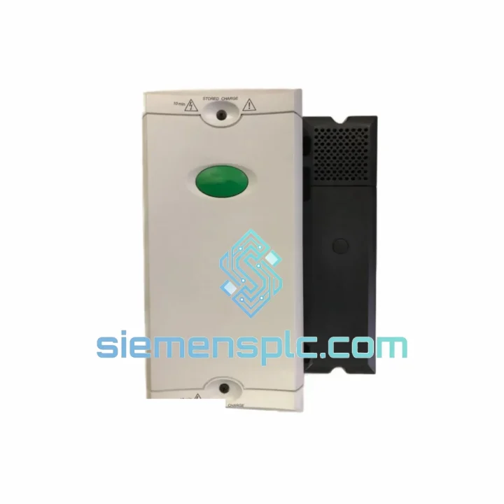
Control Techniques UNI2402 Drive Interface Module – Universal Interface Series
Universal Interface Series
Origin United Kingdom
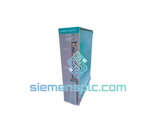
Drive Interface Module
Request verified availability, condition, replacement risk review, packing options and courier lead time for SPMC2402.
Click Request Quote and the part number is inserted into the inquiry form automatically.
Core fields for model confirmation and RFQ routing. Detailed product narrative remains below.
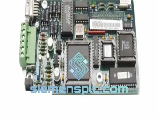
The Control Techniques SPMC2402 belongs to the Commander product family and is engineered for industrial applications where scalar V/Hz control is architecturally inadequate. Its closed-loop flux vector control algorithm decomposes the stator current into two orthogonal components in the synchronously rotating d-q reference frame: the torque-producing component (Iq) and the flux-producing component (Id). Each component is regulated by an independent PI controller executing at the DSP’s control loop update rate. The result is decoupled torque and flux control — a property that allows the drive to deliver rated torque at near-zero shaft speed without the current derating penalty inherent to open-loop scalar drives.
When the SM-Encoder Plus option module is fitted, the SPMC2402 closes the speed loop using quadrature incremental encoder feedback. Under steady-state conditions, speed regulation accuracy reaches ±0.01% of rated speed — approximately 50× tighter than the ±0.5% typical of open-loop sensorless vector modes. This level of speed holding is a process requirement in winding, hoisting, and precision positioning applications where load-induced speed droop directly translates to dimensional or tension errors in the product being processed.
The power stage is a three-phase IGBT inverter bridge with individual gate driver channels per switch. Each gate driver incorporates desaturation detection circuitry that monitors the collector-emitter voltage of its IGBT during the on-state conduction interval. A voltage excursion above the desaturation threshold — indicating an overcurrent or short-circuit condition — triggers a controlled gate shutdown within sub-microsecond response time, before fault energy can propagate to the DC bus capacitor bank or cause thermal runaway at the IGBT junction. This per-switch protection granularity is not achievable with module-level protection alone.
The DC bus capacitor bank provides both supply ripple filtering and a defined energy reservoir for kinetic energy ride-through. Upon detecting a supply undervoltage event, the drive’s firmware transitions to a controlled regenerative deceleration mode: the inverter applies a braking torque vector, converting the motor’s rotational kinetic energy back to electrical energy and sustaining the DC bus above the minimum operating threshold. Depending on load inertia, this extends the effective ride-through window to 50–200 ms — a range that covers the majority of voltage dip events defined in IEC 61000-4-11 Class 3 immunity criteria and eliminates nuisance trips in installations with marginal supply quality.
The analog input conditioning stage uses differential amplifiers with a common-mode rejection ratio (CMRR) exceeding 60 dB at line frequency. Ground potential differences between the drive and the signal source — which can reach several volts in large installations with distributed earthing — are rejected without introducing offset errors into the speed reference signal. Both configurable analog inputs accept 0–10 V or 4–20 mA signals at 10-bit resolution and can be independently scaled, offset, and low-pass filtered via drive parameters, eliminating the need for external signal conditioning hardware in most installations.
Thermal management combines forced-air cooling through the heatsink fin array with a predictive thermal derating algorithm. An NTC thermistor mounted on the heatsink provides continuous temperature measurement to the drive’s thermal model. Rather than executing a hard trip at a fixed over-temperature threshold, the firmware progressively reduces PWM switching frequency and output current limit as heatsink temperature approaches the thermal ceiling. This graduated response maintains drive operation at reduced capacity during thermal stress events, avoiding the process disruption of an abrupt trip in continuous-duty applications where a controlled slowdown is operationally preferable to an unplanned stop.
The software-based motor thermal model is parameterized by motor rated current, thermal time constant (I²t), and ambient temperature. It integrates squared output current over time, accumulating thermal state across multiple start/stop cycles and accounting for reduced cooling capacity at low shaft speeds in self-cooled motors. This model operates in parallel with the hardware PTC/NTC thermistor input, providing dual-layer motor protection: the model detects gradual thermal accumulation across a duty cycle; the thermistor input responds to acute overtemperature events such as blocked ventilation or locked-rotor conditions.
Real-time Stock & RFQ: [email protected] | WhatsApp: +86 18359268345
| Parameter | Specification |
|---|---|
| Part Number | SPMC2402 |
| Brand | Control Techniques (Nidec Industrial Automation) |
| Series | Commander |
| Drive Topology | Three-phase IGBT inverter, uncontrolled diode rectifier front-end |
| Control Modes | Closed-loop flux vector (encoder); Open-loop sensorless vector; V/Hz scalar |
| Input Supply Voltage | Three-phase AC — confirm exact band (200–240 V or 380–480 V) from unit nameplate |
| Output Frequency Range | 0 – 1000 Hz (motor rated frequency typically 50 / 60 Hz) |
| PWM Switching Frequency | 3 kHz – 12 kHz, user-selectable; higher settings reduce audible noise, increase switching loss |
| Speed Regulation — Closed-Loop | ±0.01% of rated speed (SM-Encoder Plus fitted) |
| Speed Regulation — Open-Loop | ±0.5% of rated speed (sensorless vector mode) |
| Analog Inputs | 2 × configurable: 0–10 V / 4–20 mA, 10-bit resolution, differential input stage, CMRR > 60 dB |
| Digital Inputs | 6 × programmable, 24 V DC logic; run/stop, preset speeds, fault reset, interlock functions |
| Relay Outputs | 2 × Form C relay; configurable for drive healthy, at-speed, fault, and custom logic states |
| Analog Output | 1 × 0–10 V or 4–20 mA, configurable source: speed, current, torque, or power |
| Fieldbus — Standard | Modbus RTU via RS-485 (integrated) |
| Fieldbus — Optional | PROFIBUS DP, DeviceNet, EtherNet/IP, CANopen (via SM option modules) |
| Encoder Feedback Interface | SM-Encoder Plus option module; quadrature incremental, 5 V or 15 V encoder supply |
| Protection Functions | Overcurrent, overvoltage, undervoltage, phase loss, ground fault, motor PTC/NTC overtemperature, drive overtemperature, stall detection, desaturation per IGBT switch |
| Enclosure Rating | IP20 (panel-mount) |
| Ambient Operating Temperature | 0 °C to +40 °C continuous; derate above 40 °C per manufacturer derating curve |
| Storage Temperature | −40 °C to +60 °C |
| Relative Humidity | ≤ 95% RH, non-condensing |
| Altitude | ≤ 1000 m without derating; 1% current derating per 100 m above 1000 m |
| EMC Compliance | EN 55011 Class C2 (conducted emissions); IEC 61000-4-11 Class 3 (voltage dip immunity) |
| Safety Certifications | CE (EMC Directive 2014/30/EU; LVD 2014/35/EU); UL Listed |
| Warranty | 12 months from date of shipment |
Gate Driver Galvanic Isolation Architecture: Each of the six IGBT gate driver channels is isolated from the DSP control board using optocoupler or transformer-coupled isolation barriers rated for reinforced insulation per IEC 60664-1. This topology prevents high-voltage switching transients — with dV/dt rates that can exceed 5 kV/µs in fast-switching configurations — from coupling back into the control logic ground plane via parasitic capacitance paths. Each gate driver channel is powered by an independent isolated DC-DC converter, maintaining consistent gate threshold margins across the full IGBT junction temperature range (−40 °C to +150 °C) and ensuring uniform switching loss distribution across all six switches of the inverter bridge.
EMC Layout and Conducted Emission Suppression: The PCB layout physically segregates the high-frequency power switching stage from the analog and digital control circuitry using a grounded copper shield plane. This segregation reduces capacitive coupling of PWM switching transients — which contain significant harmonic energy from the fundamental switching frequency up through the 30 MHz conducted emission limit — into the analog signal conditioning paths. The internal EMC filter comprises common-mode chokes wound on high-permeability ferrite cores selected for effective attenuation across the 150 kHz – 30 MHz conducted emission band, combined with X/Y capacitors for differential and common-mode filtering. The combined filter architecture achieves EN 55011 Class C2 compliance on the supply input without requiring an external line reactor in most standard installation configurations.
DC Bus Ride-Through State Machine: The DC bus capacitor bank is sized to provide a defined energy reservoir expressed in joules per kilowatt of drive rating. During normal operation, the uncontrolled diode rectifier maintains bus voltage at approximately 1.35 × VLL(rms). Upon supply interruption, the firmware’s ride-through state machine monitors bus voltage decay rate and transitions to regenerative braking mode when the bus drops below a configurable threshold. The inverter applies a controlled braking torque vector, converting the motor’s rotational kinetic energy to electrical energy and feeding it back to the DC bus. The state machine continuously adjusts the braking torque magnitude to maximize energy recovery while maintaining motor current within the drive’s rated output current envelope.
Dual-Layer Motor Thermal Protection: The software thermal model integrates I²t over time with a configurable thermal time constant, accumulating thermal state across multiple start/stop cycles. At low shaft speeds, the model applies a speed-dependent cooling derating factor to account for the reduced airflow of self-cooled motors — a correction that is absent in simple I²t implementations and that prevents thermal damage in applications with frequent low-speed operation. The hardware PTC/NTC thermistor input provides a parallel protection channel with direct measurement of winding temperature, responding to acute overtemperature events that the thermal model cannot predict from current data alone, such as blocked ventilation or ambient temperature excursions.
Each Control Techniques SPMC2402 unit dispatched from our Xiamen, China facility is sourced through verified supply channels with full traceability to the original manufacturer’s production batch. Authenticity verification covers serial number cross-referencing against manufacturer records, physical inspection of holographic authentication labels, terminal block markings, and PCB revision codes — the combination of which distinguishes genuine units from counterfeit product circulating in uncontrolled grey-market channels.
Pre-shipment inspection includes visual examination of housing and connector integrity, terminal block seating, and label legibility. Where operationally feasible, power-on functional verification confirms parameter menu access and basic drive response prior to packaging. Units are packed in anti-static foam-lined cartons with moisture-barrier inner packaging, suitable for air freight, sea freight, and express courier transit without risk of electrostatic discharge damage to the control electronics.
From Xiamen, shipments reach destinations across Southeast Asia, the Middle East, Europe, North America, and South America via DHL Express, FedEx International Priority, and freight forwarder networks. Export documentation — commercial invoice, packing list, certificate of origin, and customs declaration — is prepared in compliance with destination country import requirements. DDP (Delivered Duty Paid) terms are available for qualified buyers. Standard express delivery to major industrial hubs completes within 3–7 business days from order confirmation. All units carry a 12-month warranty against manufacturing defects from the date of shipment, with replacement dispatch or credit note issuance subject to fault verification.
Email: [email protected]
WhatsApp: +86 18359268345
Web: siemensplc.com
Location: Xiamen, China
© 2026 siemensplc.com. All rights reserved.
We check the full part number, brand, series and visible nameplate information before quotation.
Sales confirms stock path, condition option, quantity and realistic lead time for export dispatch.
DHL, FedEx, UPS or buyer courier arrangements can be reviewed with packing requirements.
Similar brand or category products for fast comparison and multi-item RFQ lists.