BERGER LAHR
RFQ Ready
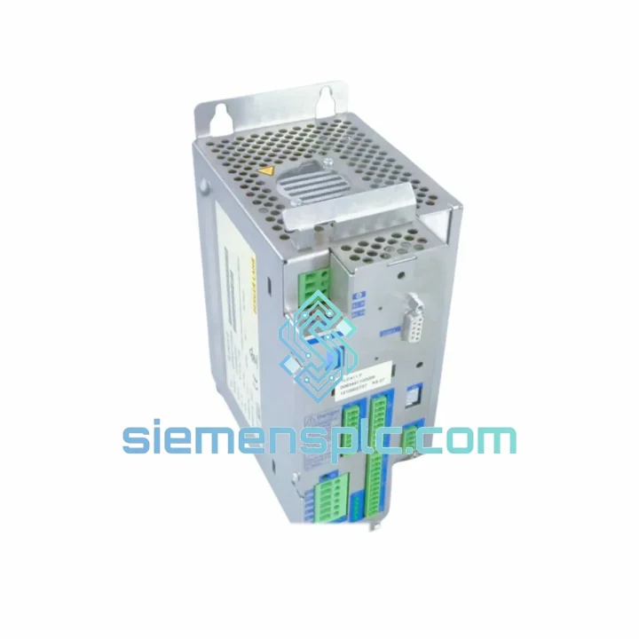
Berger Lahr TLC4362D312151 Servo Drive – TLC Series
TLC Series
Origin US
Servo Drive
Request verified availability, condition, replacement risk review, packing options and courier lead time for IFM/TLC.
Click Request Quote and the part number is inserted into the inquiry form automatically.
Core fields for model confirmation and RFQ routing. Detailed product narrative remains below.
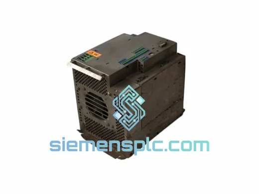
The BERGER LAHR TLC411F is a two-phase stepper motor drive unit belonging to the IFM/TLC product family, engineered under the BERGER LAHR motion control brand — a division later absorbed into Schneider Electric’s industrial drive portfolio. Within a closed-loop or open-loop motion system, the TLC411F sits at the power-conversion and phase-sequencing layer: it receives step and direction pulses from an upstream motion controller or PLC digital output, translates those pulses into a precise electrical angle sequence, and delivers regulated phase current to the stepper motor windings at the configured micro-step resolution. This functional position makes the TLC411F the deterministic bridge between digital trajectory commands and physical rotor displacement, with no intermediate protocol conversion that would otherwise introduce latency or positional ambiguity.
The TLC series was developed for European OEM machine builders operating in sectors where motion repeatability, cabinet space density, and long service intervals are primary design constraints. Documented field deployments include CNC machining centres, textile warp-beam drives, semiconductor wafer-handling gantries, pharmaceutical packaging indexers, and precision laboratory automation stages. The unit’s 2,130 g mass reflects a robust internal power stage and integrated aluminium heatsink rather than a lightweight consumer-grade assembly — a deliberate design choice for continuous-duty industrial environments.
Real-time Stock & RFQ: [email protected] | WhatsApp: +86 18359268345
| Parameter | Specification |
|---|---|
| Part Number / SKU | TLC411F |
| Brand | BERGER LAHR (Schneider Electric Motion) |
| Product Family | IFM / TLC Series |
| Device Classification | Two-Phase Stepper Motor Drive Controller |
| Motor Compatibility | 2-phase bipolar stepper motors; NEMA 23 / NEMA 34 frame class |
| Command Interface | Step / Direction pulse input — TTL-compatible logic levels (5 V / 24 V selectable) |
| Micro-step Resolution | Configurable divisor table (full-step, half-step, 1/4, 1/8, 1/16 — confirm with OEM datasheet) |
| DC Supply Voltage | 24 VDC or 48 VDC regulated (confirm exact range with OEM datasheet) |
| Phase Output Current | Rated per-phase current — refer to OEM datasheet for exact amperage |
| Current Regulation Method | Fixed-frequency chopper PWM with sinusoidal micro-step DAC reference |
| Isolation | Opto-isolated step/direction input stage |
| Mounting | 35 mm DIN rail / panel mount |
| Unit Weight | 2,130 g (4.70 lb) |
| Operating Temperature | 0 °C to +50 °C ambient (refer to OEM datasheet for derating curve) |
| Storage Temperature | −25 °C to +70 °C |
| Relative Humidity | 5 % to 95 % non-condensing |
| Certifications | CE — EU Low Voltage Directive, Machinery Directive |
| EMC Standard | EN 61800-3 (Power Drive Systems — EMC requirements) |
| Safety Standard | IEC 60204-1 (Electrical equipment of machines) |
| Country of Origin | Germany |
| Warranty | 12 months from date of dispatch |
The TLC411F’s internal architecture is partitioned into three discrete functional blocks: the input signal conditioning stage, the phase-sequencing and micro-step DAC, and the H-bridge power output stage. Understanding each block’s design rationale clarifies why the drive performs reliably in electrically noisy industrial cabinets.
Input Signal Conditioning and Opto-Isolation: The step and direction input path is galvanically isolated from the drive’s internal power ground via an opto-coupler stage. This separation eliminates ground-loop currents — a primary source of spurious step pulses in mixed-signal cabinets where servo drives, contactors, and PLC I/O share a common enclosure. The opto-coupler’s forward current is set to operate within the linear region of its transfer characteristic, ensuring consistent pulse-width fidelity across the full rated step frequency range. At maximum step rates, the opto-coupler propagation delay is accounted for in the input filter time constant, preventing pulse-stretching artefacts that would corrupt the position register in high-speed traverse moves.
Phase Sequencing and Sinusoidal Micro-step DAC: Each incoming step pulse advances the electrical angle pointer by one micro-step increment. A look-up table (LUT) maps the current electrical angle to a pair of sinusoidal current references — one per motor phase — which are fed to the current regulators. This approach approximates a continuously rotating magnetic field rather than the discrete 90° jumps of full-step operation. The practical consequence is a significant reduction in mid-range resonance: the speed band in which the motor’s mechanical resonant frequency coincides with the electrical drive frequency is narrowed, and the excitation amplitude at that frequency is reduced. For applications traversing a wide speed range — such as packaging indexers with variable product pitch — this means fewer stall events and lower audible noise without requiring active damping algorithms in the motion controller.
H-Bridge Power Stage and Chopper Current Regulation: Each motor phase is driven by a dedicated H-bridge constructed from power MOSFETs selected for low drain-source on-resistance (RDS(on)). Low RDS(on) reduces I²R conduction losses at rated current, which directly lowers the thermal load on the integrated heatsink and extends MOSFET junction life under continuous-duty operation. The chopper current regulator compares actual winding current — measured via a low-side shunt resistor — against the sinusoidal DAC reference and adjusts PWM duty cycle on a cycle-by-cycle basis. This closed-loop current control maintains constant torque output independent of winding back-EMF variation across the speed range, compensating for the inductance-driven current roll-off that causes torque loss in unregulated drives at mid and high speeds. The chopper frequency is set above 20 kHz to keep switching noise outside the audible spectrum, a requirement in laboratory and medical-adjacent automation environments.
EMC Layout and Chassis Bonding: The PCB layout follows IEC 61800-3 Category C2 practice: power and signal routing layers are segregated, decoupling capacitors are placed at each MOSFET switching node to suppress high-frequency transients, and the chassis ground is bonded directly to the DIN rail mounting point via a low-impedance copper strap. This provides a defined return path for common-mode currents induced by the PWM switching edges, preventing those currents from coupling into adjacent signal wiring. In most standard cabinet installations, no additional external EMC filter is required to meet EN 61800-3 conducted emission limits.
Thermal Management: The drive’s aluminium heatsink is integrated into the housing extrusion, conducting heat from the MOSFET packages to the ambient air via natural convection. The 2,130 g unit mass is partly attributable to the heatsink volume, which provides sufficient thermal capacitance to absorb short-duration overload events — such as acceleration peaks in high-inertia loads — without triggering thermal shutdown. For continuous high-current applications, forced-air cooling of the cabinet interior is recommended to maintain heatsink temperature within the derating threshold specified in the OEM datasheet.
Every BERGER LAHR TLC411F unit dispatched from our Xiamen, China facility passes a structured pre-shipment inspection protocol before packaging. Physical inspection covers housing integrity, connector pin geometry and retention force, label legibility, and absence of corrosion, impact damage, or moisture ingress. Where unit condition permits, a power-on functional check confirms correct drive initialisation and response to enable/disable signals. Units are individually sealed in anti-static polyethylene bags with silica gel desiccant and humidity indicator cards, then placed in foam-lined corrugated cartons rated for international air freight handling. Each shipment is sealed with tamper-evident tape and accompanied by a commercial invoice, packing list, and certificate of origin to support customs clearance in all major import jurisdictions.
Logistics from Xiamen reach major industrial hubs on the following typical transit schedules via express air freight: Southeast Asia 3–5 business days; Europe 5–8 business days; North America 5–7 business days; Middle East 4–6 business days; Australia and Oceania 5–7 business days. Express courier options via DHL, FedEx, and UPS are available for machine-down emergency situations. All shipments are tracked end-to-end, with tracking numbers provided within 24 hours of dispatch confirmation. Export documentation is prepared in full compliance with Chinese customs regulations and destination-country import requirements. The 12-month warranty covers functional failure under normal operating conditions and is supported directly by our technical team in Xiamen, with no third-party intermediary required for warranty claims.
Email: [email protected]
WhatsApp: +86 18359268345
Web: siemensplc.com
Location: Xiamen, China
© 2026 siemensplc.com. All rights reserved.
We check the full part number, brand, series and visible nameplate information before quotation.
Sales confirms stock path, condition option, quantity and realistic lead time for export dispatch.
DHL, FedEx, UPS or buyer courier arrangements can be reviewed with packing requirements.
Similar brand or category products for fast comparison and multi-item RFQ lists.