ProvibTech
RFQ Ready
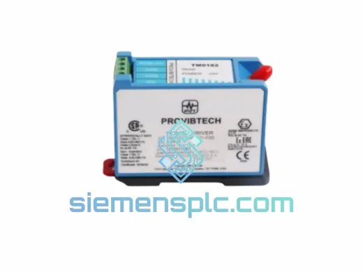
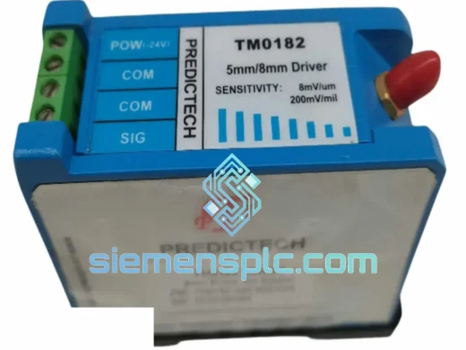
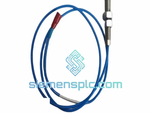
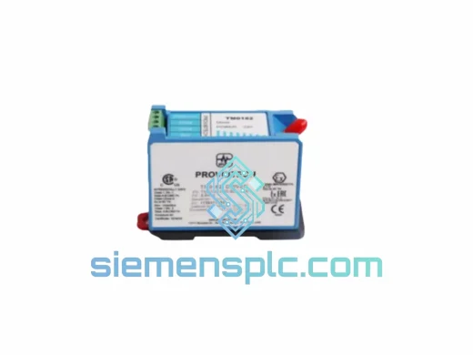
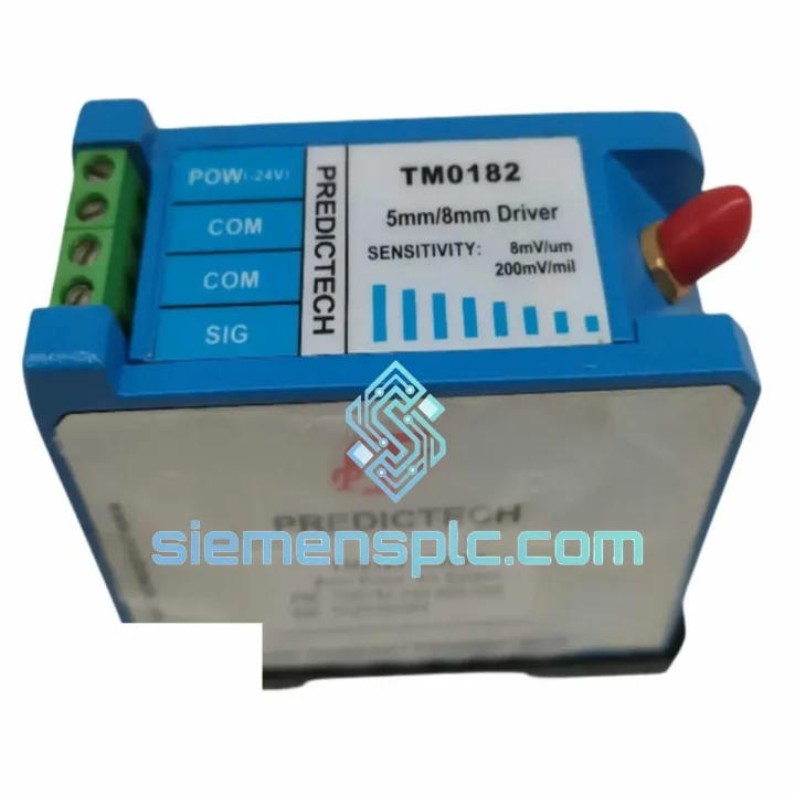
PROVIBTECH TM0182-A50-B00-C00 Proximity Sensor
TM0182 Series
Origin US
Vibration & Proximity Sensor
Request verified availability, condition, replacement risk review, packing options and courier lead time for TM201-A02-B00-C00-000-E00-G00.
Click Request Quote and the part number is inserted into the inquiry form automatically.
Core fields for model confirmation and RFQ routing. Detailed product narrative remains below.
The PROVIBTECH TM201-A02-B00-C00-000-E00-G00 is a factory-configured, dual-channel vibration signal conditioning module designed for continuous deployment in turbomachinery protection and rotating equipment condition monitoring applications. The configuration suffix A02-B00-C00-000-E00-G00 defines the hardware topology at the factory level: A02 specifies a two-channel input architecture; B00, C00, and E00 encode the output signal range, relay variant, and communication interface selection respectively; G00 designates the standard enclosure and mounting format. This suffix-encoded parameterization eliminates the need for field-level hardware jumper changes after installation, reducing commissioning time and the risk of misconfiguration in multi-module rack assemblies.
Within a rotating machinery protection loop, the TM201-A02-B00-C00-000-E00-G00 occupies the signal chain segment between the transducer junction box and the DCS or SIS analog input subsystem. It accepts raw electrical signals from eddy-current proximity probes (shaft displacement), velocity transducers (casing vibration), or piezoelectric accelerometers, and delivers conditioned 4–20 mA process outputs alongside relay-driven alert and danger states. The module simultaneously drives a buffered ±10 VDC transducer replica output at low source impedance, allowing a portable spectrum analyzer or online vibration data collector to connect in parallel without loading the primary measurement circuit — a requirement in API 670-compliant machinery protection architectures where measurement integrity must not be compromised during route-based data acquisition.
Gap voltage monitoring for eddy-current proximity probe channels operates continuously in the background. If the probe gap voltage drifts outside the calibrated linear range (−2 VDC to −22 VDC), the module flags a transducer fault condition via a dedicated status output, preventing the DCS from interpreting a probe installation error as a zero-vibration reading. This active transducer health supervision is a functional requirement in API 670 Section 5.3 and is implemented here in hardware rather than firmware, ensuring the check remains active regardless of microcontroller state.
Real-time Stock & RFQ: [email protected] | WhatsApp: +86 18359268345
| Parameter | Specification |
|---|---|
| Manufacturer | PROVIBTECH |
| Full Part Number | TM201-A02-B00-C00-000-E00-G00 |
| Platform Series | TM201 Vibration Monitoring Platform |
| Input Channel Count (A02) | 2 independent channels; eddy-current proximity probe, velocity transducer, or accelerometer |
| Probe Supply Voltage | −24 VDC regulated, short-circuit protected, current-limited at 25 mA per channel |
| Gap Voltage Monitoring Range | −2 VDC to −22 VDC; hardware fault flag outside range |
| Analog Process Output | 4–20 mA, NAMUR NE43 compliant, max load 500 Ω |
| Buffered Transducer Output | ±10 VDC, source impedance <100 Ω, isolated from process output |
| Measurement Frequency Range | 0.5 Hz – 10 kHz (channel-dependent, factory-set per configuration code) |
| RMS Conversion Accuracy | ±1% of full scale; crest factor tolerance 3:1 |
| Peak-Hold Capture Window | 1 ms hardware capture, independent of RMS path |
| Alert / Danger Relay Output | 2 × SPDT relay per channel; 5 A @ 250 VAC; gold-flashed contacts |
| Relay Time-Delay Range | 0–60 s, independently configurable per relay |
| Relay Response Latency | ≤ 100 ms from threshold crossing to contact state change |
| Galvanic Isolation Withstand | 500 VDC, field circuit to internal bus |
| Power Supply Input | 18–32 VDC, reverse-polarity protected |
| Power Consumption | ≤ 8 W (fully loaded, both channels active) |
| Operating Temperature | −20 °C to +70 °C |
| Storage Temperature | −40 °C to +85 °C |
| Relative Humidity | 5%–95% RH, non-condensing |
| EMC Standards | IEC 61000-4-2 (ESD Level 3), IEC 61000-4-4 (EFT Level 3), IEC 61000-4-5 (Surge Level 3) |
| Watchdog Fail-Safe | Hardware watchdog; relay de-energized within 200 ms on firmware fault |
| Mounting | DIN-rail (EN 60715) or 19″ rack-mount; IP20 enclosure |
| Weight | 520 g |
| Country of Origin | China |
| Warranty | 12 months from confirmed dispatch date |
Input Stage — Transformer-Coupled Galvanic Isolation: The TM201-A02-B00-C00-000-E00-G00 employs transformer-coupled galvanic isolation at the field input boundary, rated at 500 VDC withstand between the transducer circuit and the module’s internal signal processing bus. This topology severs the ground-loop current path that forms when proximity probe cable shields share conduit with motor power wiring — a common installation condition in compressor trains where cable routing options are constrained by structural geometry. Ground-loop currents at 50 or 60 Hz inject directly into the measurement band for low-speed machinery (300–3600 RPM), where shaft displacement frequencies fall in the 5–60 Hz range. Transformer coupling eliminates this interference source at the hardware level rather than relying on software filtering, which would introduce phase lag into the measurement and degrade the accuracy of 1× and 2× vibration vector calculations used in balancing diagnostics.
Signal Conditioning — Dual-Path Architecture (RMS + Peak-Hold): After the isolation stage, the conditioned signal enters a precision active bandpass filter network with factory-set corner frequencies matched to the measurement variable encoded in the configuration suffix. For displacement channels, the filter is low-pass dominant with a corner frequency below 1 kHz to suppress high-frequency noise from gear mesh events that would otherwise bias the displacement reading. For velocity channels, a bandpass response spanning 10 Hz to 1 kHz captures the primary casing vibration energy while rejecting DC drift from thermal expansion of the transducer mounting structure. The filtered signal then feeds two parallel processing paths: a true-RMS converter with a 3:1 crest factor tolerance for continuous amplitude tracking, and a 1 ms peak-hold circuit that captures transient amplitude spikes independently. The peak-hold output drives the danger relay comparator directly, ensuring that a high-amplitude transient of duration shorter than the RMS averaging window — such as a blade-loss event or a sudden rub contact — still triggers the protection relay without waiting for the RMS value to respond.
EMC Hardening — TVS Array and Relay Contact Protection: The relay driver stage incorporates a transient voltage suppressor (TVS) array on each relay coil drive line, clamping inductive kickback from relay de-energization to ±36 V within 5 ns. This protects the relay driver transistors from avalanche breakdown during high-frequency switching cycles in applications where the relay is used as a pulsed output rather than a latched alarm. The relay contacts are gold-flashed to maintain low contact resistance (<100 mΩ) at low-level signal currents — relevant when the relay drives a PLC digital input module operating at 5 VDC logic levels rather than a 24 VDC solenoid coil. A hardware watchdog timer monitors the internal microcontroller’s execution cycle; if the watchdog detects a missed heartbeat — indicating a firmware hang or stack overflow — it forces all relay outputs to the de-energized state within 200 ms. This fail-safe behavior is implemented in dedicated hardware logic independent of the microcontroller, satisfying the SIL 1 partial requirement for a single-channel protection function without additional external voting logic.
Power Supply Architecture — Wide-Range Input with Sag Tolerance: The 18–32 VDC input range is not simply a specification margin; it reflects a deliberate design choice to accommodate the voltage sag conditions that occur in large control panels during simultaneous load switching events. When multiple solenoid valves or motor starters energize simultaneously, the 24 VDC bus can sag to 18–19 V for 20–50 ms. A module with a narrower input range (e.g., 21.6–26.4 VDC per IEC 61131-2 standard) would reset during this sag, momentarily de-energizing protection relays and creating a false “safe” indication. The TM201’s extended lower limit prevents this failure mode without requiring an external UPS or voltage stabilizer in the panel design.
Each PROVIBTECH TM201-A02-B00-C00-000-E00-G00 unit dispatched from our Xiamen, China facility is sourced through traceable procurement channels and subjected to a structured pre-shipment inspection sequence. The inspection protocol covers: label and firmware revision verification against OEM reference data; power-on functional test of analog output accuracy to ±0.1% full-scale tolerance; relay contact resistance measurement with a 100 mΩ acceptance limit; gap voltage monitoring circuit verification across the full −2 VDC to −22 VDC range; and final packaging in anti-static, moisture-barrier materials with a silica gel desiccant pack rated for 90-day transit protection.
Xiamen’s logistics infrastructure — direct access to Xiamen Gaoqi International Airport and the Port of Xiamen — supports same-day handover to DHL Express, FedEx International Priority, and UPS Worldwide Express for time-critical orders. In-stock units ship within 1–3 business days of payment confirmation. Standard export documentation is prepared as a matter of course: commercial invoice, packing list, certificate of origin, and HS code 8543.70 classification declaration. For consolidated project shipments, sea freight LCL consolidation from Xiamen port is available, with typical transit times of 18–25 days to Northern European ports, 14–18 days to Southeast Asian destinations, and 20–28 days to East Coast North American ports.
The 12-month warranty covers dead-on-arrival failures and early-life defects attributable to manufacturing. Warranty claims are handled directly by our technical team, with a target replacement dispatch of 5 business days from confirmed fault diagnosis — no third-party RMA routing that extends equipment downtime on the plant floor.
Email: [email protected]
WhatsApp: +86 18359268345
Web: siemensplc.com
Location: Xiamen, China
© 2026 siemensplc.com. All rights reserved.
We check the full part number, brand, series and visible nameplate information before quotation.
Sales confirms stock path, condition option, quantity and realistic lead time for export dispatch.
DHL, FedEx, UPS or buyer courier arrangements can be reviewed with packing requirements.
Similar brand or category products for fast comparison and multi-item RFQ lists.