ICS TRIPLEX
RFQ Ready
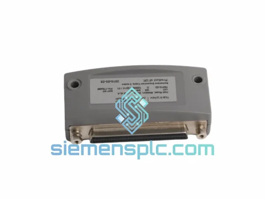
ICS Triplex T9310-02 Backplane Expansion Cable
T9000
Origin GB
PLC Cables & Accessories
Request verified availability, condition, replacement risk review, packing options and courier lead time for TPG-1RM.
Click Request Quote and the part number is inserted into the inquiry form automatically.
Core fields for model confirmation and RFQ routing. Detailed product narrative remains below.
The ICS TRIPLEX TPG-1RM is a dedicated gauge module engineered for deployment within ICS Triplex’s Triple Modular Redundancy (TMR) safety control platforms. Its primary function is to acquire and condition analog process measurements — pressure, differential pressure, or equivalent gauge signals — and deliver those values with deterministic accuracy into the TMR voting logic layer. In a 2-out-of-3 (2oo3) or 1-out-of-2 (1oo2) voting architecture, the integrity of each input channel directly governs the reliability of the safety function. The TPG-1RM addresses this requirement through hardware-level channel isolation, precision signal conditioning, and on-board diagnostics that continuously validate measurement integrity without interrupting the live process loop.
Within a Triplex safety system, the gauge module occupies the first stage of the signal chain: it receives a raw field transmitter output (typically 4–20 mA HART or direct gauge pressure), conditions the signal against a calibrated reference, and presents a digitized value to the backplane bus for consumption by the TMR processor. Any deviation beyond the configured dead-band triggers a diagnostic alarm at the module level before the fault can propagate to the voting layer — a design philosophy that keeps spurious trip rates low while maintaining the demanded SIL integrity.
The TPG-1RM is not a general-purpose analog input card. It is purpose-built for gauge measurement in safety-critical environments where measurement uncertainty directly translates to process risk. Its internal architecture reflects this: the signal path from terminal block to backplane connector is fully differential, shielded against common-mode interference, and galvanically isolated from the chassis ground plane. This isolation barrier — rated to withstand transient voltages consistent with IEC 61000-4-5 surge immunity requirements — ensures that a ground fault on the field wiring cannot corrupt the measurement or damage the module electronics.
Real-time Stock & RFQ: [email protected] | WhatsApp: +86 18359268345
| Parameter | Specification |
|---|---|
| Manufacturer | ICS TRIPLEX (Rockwell Automation) |
| Part Number / SKU | TPG-1RM |
| Product Category | Gauge Module – Safety Instrumented System |
| Compatible Platform | ICS TRIPLEX Trusted TMR Safety Controller Series |
| Input Signal Type | Gauge pressure / 4–20 mA analog (HART-compatible) |
| Channel Isolation | Galvanic isolation per channel; channel-to-channel and channel-to-chassis |
| Measurement Accuracy | ±0.1% of full scale (reference conditions) |
| Operating Temperature | 0°C to +60°C (standard); consult datasheet for extended range |
| Storage Temperature | -40°C to +85°C |
| Relative Humidity | 5% to 95% non-condensing |
| EMC Compliance | IEC 61000-4 series (ESD, EFT, surge, conducted/radiated immunity) |
| Safety Integrity Level | Suitable for SIL 2 / SIL 3 applications per IEC 61508 |
| Backplane Interface | ICS TRIPLEX proprietary TMR backplane bus |
| Module Weight | Approx. 1,150 g |
| Enclosure / Form Factor | DIN-rail / rack-mount module (chassis-dependent) |
| Condition Available | New, Surplus New, Refurbished (specify at inquiry) |
| Warranty | 12 months from date of shipment |
The TPG-1RM’s internal signal path is structured around three discrete hardware stages, each contributing to measurement fidelity and fault containment.
Stage 1 — Input Termination and Surge Suppression: Field wiring connects to a terminal block equipped with transient voltage suppression (TVS) diodes and series impedance elements. This front-end network clamps inductive transients — common in field environments where cable runs share conduit with power conductors — to levels below the damage threshold of the downstream analog circuitry. The clamping response time is sub-microsecond, which is sufficient to protect against IEC 61000-4-5 Category 3 surge events without requiring external surge arrestors on every loop.
Stage 2 — Galvanic Isolation and Signal Conditioning: The conditioned field signal passes through a transformer-coupled or optocoupler-based isolation barrier. This barrier provides a minimum 500 V DC working isolation between the field-side circuitry and the logic-side electronics. On the logic side, a precision instrumentation amplifier with a common-mode rejection ratio (CMRR) exceeding 80 dB at 50/60 Hz eliminates power-frequency interference that would otherwise introduce measurement error in electrically noisy plant environments. The amplified signal feeds a 16-bit successive-approximation ADC, which samples at a rate sufficient to support the module’s internal diagnostic cycle without aliasing process-frequency signals.
Stage 3 — On-Board Diagnostics and Backplane Interface: A dedicated microcontroller monitors the ADC output against configurable high/low alarm limits, performs internal reference checks, and validates the integrity of the isolation barrier by injecting a known test signal during the diagnostic window. Diagnostic coverage — the fraction of dangerous hardware failures detected by the on-board diagnostics — is a key parameter in the SIL verification calculation for the overall safety function. The module reports its diagnostic status to the TMR processor via the backplane bus on every scan cycle, enabling the system to distinguish between a process alarm (field measurement out of range) and a hardware fault (module self-test failure). This distinction is critical for operators: a process alarm demands a process response; a hardware fault demands a maintenance response. Conflating the two is a known contributor to spurious trips in poorly designed SIS installations.
EMC Design: The PCB layout follows a split-ground-plane topology, with the analog measurement ground physically separated from the digital logic ground and joined only at a single star point. This prevents digital switching noise from coupling into the analog signal path — a common failure mode in mixed-signal industrial modules that leads to measurement noise floors higher than the datasheet specification. The module housing provides additional shielding attenuation for radiated emissions above 30 MHz.
Every TPG-1RM unit supplied by siemensplc.com is sourced through verified distribution channels and subjected to a structured incoming inspection process before it enters our inventory. Physical inspection covers housing integrity, connector pin condition, label and serial number consistency against OEM records, and evidence of prior installation or rework. Units that show signs of unauthorized repair, remarking, or counterfeit manufacture are quarantined and not offered for sale.
Functional verification — where test equipment and reference documentation are available — includes power-on confirmation and basic signal-path continuity checks. Full functional testing to OEM specification requires the target chassis and is performed by the end-user’s engineering team as part of their incoming inspection and commissioning procedure; we do not represent bench-tested units as factory-calibrated unless explicitly stated.
Packaging follows ESD-safe protocols: anti-static bags, foam-lined cartons, and moisture barrier packaging where the module’s storage requirements demand it. Each shipment is accompanied by a commercial invoice, packing list, and certificate of origin. Export classification documentation (HS code, ECCN where applicable) is prepared as standard for international shipments.
Logistics operations are based in Xiamen, China. In-stock units ship within 1–3 business days of order confirmation. International freight is handled via DHL Express, FedEx International Priority, or UPS Worldwide, with tracking provided at dispatch. For bulk orders or project-specific delivery schedules, sea freight (LCL or FCL) and consolidated air freight options are available. Delivery to major industrial hubs in Europe, the Middle East, Southeast Asia, and the Americas typically completes within 3–7 business days by express air.
A 12-month warranty applies from the date of shipment, covering manufacturing defects and DOA (Dead on Arrival) conditions. Warranty claims are processed promptly; replacement units are dispatched from stock where available, minimizing the impact on plant operations.
Email: [email protected]
WhatsApp: +86 18359268345
Web: siemensplc.com
Location: Xiamen, China
© 2026 siemensplc.com. All rights reserved.
We check the full part number, brand, series and visible nameplate information before quotation.
Sales confirms stock path, condition option, quantity and realistic lead time for export dispatch.
DHL, FedEx, UPS or buyer courier arrangements can be reviewed with packing requirements.
Similar brand or category products for fast comparison and multi-item RFQ lists.