Reliance Electric
RFQ Ready
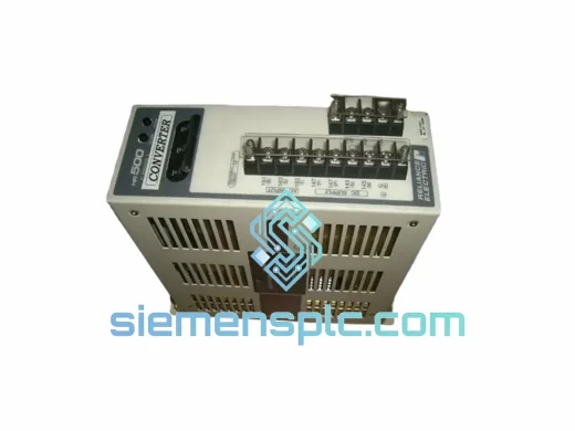
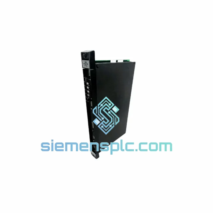
Reliance Electric WR-D4001 Power Supply Module
Drive Series
Origin US
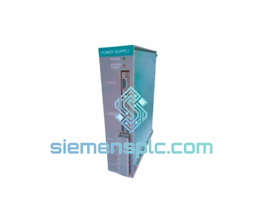
Power Supply Module
Request verified availability, condition, replacement risk review, packing options and courier lead time for 0-57412-E.
Click Request Quote and the part number is inserted into the inquiry form automatically.
Core fields for model confirmation and RFQ routing. Detailed product narrative remains below.
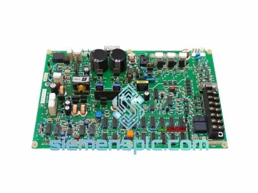
The Reliance Electric 0-57412-E is a PCB-level phase-angle regulator card engineered for integration within the inner voltage control loop of Reliance Electric DC drive platforms — including the Flex+, GV3000, and SP500 series. Its functional mandate is singular and non-negotiable: maintain DC bus voltage within OEM-specified operating tolerances by continuously computing and issuing corrective firing-angle commands to the six-pulse SCR thyristor bridge. This is not an auxiliary board. Failure of the 0-57412-E results in immediate drive trip, open-loop motor operation, or uncontrolled deceleration under regenerative load conditions.
In a standard six-pulse fully-controlled thyristor rectifier, mean DC output voltage follows the relationship Vd = Vd0 · cos(α), where Vd0 represents the theoretical no-load voltage and α is the firing angle measured from the natural commutation point. The 0-57412-E computes the instantaneous α correction required to compensate for AC supply sags, load-induced bus droop, and regenerative braking transients — all within a single 50/60 Hz half-cycle. This sub-10 ms response window is what separates a regulated DC drive from an uncontrolled rectifier.
Real-time Stock & RFQ: [email protected] | WhatsApp: +86 18359268345
| Part Number | 0-57412-E |
| Manufacturer | Reliance Electric (Rockwell Automation legacy brand) |
| Module Classification | Phase-Controlled DC Bus Voltage Regulator Card |
| Compatible Drive Platforms | Reliance Electric Flex+, GV3000, SP500 (verify against drive BOM revision) |
| Regulation Topology | Six-pulse SCR thyristor bridge, firing-angle phase control |
| Feedback Signal | DC bus voltage sense via card-edge resistive divider network |
| Error Amplifier Reference | Temperature-compensated bandgap / precision zener reference |
| Gate Pulse Isolation | Pulse transformer galvanic isolation, gate charge 10–50 µC typical |
| Ripple Filter Corner Frequency | Tuned to pass 300 Hz fundamental (six-pulse, 50 Hz supply) |
| Form Factor | Plug-in PCB card, card-edge connector interface |
| Operating Ambient Temperature | 0 °C to +55 °C |
| Storage Temperature | −25 °C to +70 °C |
| Relative Humidity | 5 % to 95 %, non-condensing |
| EMC Compliance Reference | IEC 61800-3 Category C2 conducted/radiated environment |
| Approximate Weight | 1,100 g |
| Warranty | 12 months from confirmed shipment date |
| Country of Origin | United States of America |
| Dispatch Lead Time | 1–3 business days (subject to real-time stock confirmation) |
The 0-57412-E processes control signals across four discrete hardware stages, each with defined electrical boundaries and failure modes that field engineers must understand for accurate fault isolation.
Stage 1 — Bus Voltage Acquisition: A precision resistive divider network samples the DC bus rail directly at the card-edge interface. The sampled analog signal passes through an RC low-pass filter whose corner frequency is set to approximately 300 Hz — the fundamental ripple frequency of a six-pulse rectifier operating on a 50 Hz supply. This filter attenuates higher-order harmonics (600 Hz, 900 Hz) that would otherwise introduce phase jitter into the error amplifier, while preserving the DC component and the fundamental ripple envelope needed for accurate bus voltage measurement. Capacitor ESR and resistor tolerance in this network are critical; degraded components shift the effective corner frequency and introduce measurement error that manifests as chronic bus voltage offset.
Stage 2 — Differential Error Amplification: The filtered bus voltage signal enters a differential amplifier stage where it is compared against a temperature-compensated precision reference — either a bandgap reference IC or a two-terminal zener with thermal compensation network. The output is a signed error voltage proportional to the deviation between actual and target bus voltage. The amplifier’s closed-loop gain and bandwidth are set by the surrounding passive network to achieve a loop crossover frequency that provides adequate disturbance rejection without introducing phase margin degradation that would cause oscillatory bus voltage behavior. Gain-bandwidth product of the op-amp must be sufficient to maintain flat gain through the crossover region.
Stage 3 — Firing Angle Computation: The error signal feeds a cosine-wave intersection circuit or ramp-and-pedestal comparator synchronized to the AC supply zero-crossing. This circuit translates the analog error magnitude into a firing angle α in real time. The mathematical relationship is non-linear: equal increments of error voltage do not produce equal increments of output voltage change because of the cosine transfer function. The circuit compensates for this non-linearity through the cosine-wave shaping network, producing a linearized control characteristic across the full α operating range (typically 5° to 150° for a fully-controlled bridge). This linearization is essential for stable closed-loop operation across the full speed range of the connected DC motor.
Stage 4 — Gate Pulse Distribution and Isolation: Computed firing pulses are routed to six individual SCR gate drive circuits via pulse transformers. Each transformer provides galvanic isolation between the low-voltage control domain (typically ±15 V logic supply) and the high-voltage power stage (up to 690 V AC line-to-line). Transformer magnetizing inductance and turns ratio are selected to deliver gate charge in the range of 10–50 µC within a pulse width of 50–100 µs — sufficient to ensure reliable SCR latching under worst-case gate sensitivity conditions. Pulse transformer saturation due to DC bias from asymmetric firing patterns is prevented by the AC-coupled drive circuit topology.
PCB EMC Architecture: The board layout segregates analog signal traces from high-di/dt gate drive lines using physical separation and orthogonal routing. Ground planes are partitioned between analog and power domains with a single-point star connection at the card-edge reference pin, preventing ground loop currents from injecting noise into the error amplifier input. Decoupling capacitors at each IC supply pin address both high-frequency (100 nF X7R ceramic, self-resonant at 5–15 MHz) and mid-frequency (10 µF electrolytic) impedance requirements. These measures maintain regulation accuracy in environments with conducted EMI levels consistent with IEC 61800-3 Category C2 — the standard applicable to industrial drive installations in second environments.
Every 0-57412-E unit dispatched from our Xiamen, China facility undergoes a structured pre-shipment verification protocol before release. Visual inspection covers PCB surface condition, solder joint integrity across all through-hole and SMD joints, component marking authenticity against reference databases, and card-edge connector pin condition including contact plating wear assessment. Where functional test fixtures are available, electrical verification is performed against OEM-specified parameters, with test records available upon request for quality-critical procurement.
Anti-counterfeit screening compares component date codes, PCB silkscreen revision markings, and IC topmarks against authenticated reference units held in our technical library. For legacy industrial components in the secondary market — where counterfeit prevalence is statistically significant — this step is non-negotiable and is performed on 100 % of units, not on a sampling basis.
Units are packed in anti-static ESD shielding bags, cushioned with closed-cell polyethylene foam rated for the component weight class, and sealed in double-wall corrugated cartons with silica gel desiccant packs. Shipment is via DHL Express, FedEx International Priority, or UPS Worldwide Expedited, with full tracking provided at dispatch. Typical transit times: Europe 3–5 business days; North America 4–6 business days; Southeast Asia 2–3 business days; Middle East and Africa 5–7 business days. Incoterms EXW, FOB Xiamen, and CIF destination port are available for B2B purchase orders. All export documentation — commercial invoice, packing list, certificate of origin — is prepared in compliance with destination country import requirements. HS code classification is provided for customs pre-clearance.
Email: [email protected]
WhatsApp: +86 18359268345
Web: siemensplc.com
Location: Xiamen, China
© 2026 siemensplc.com. All rights reserved.
We check the full part number, brand, series and visible nameplate information before quotation.
Sales confirms stock path, condition option, quantity and realistic lead time for export dispatch.
DHL, FedEx, UPS or buyer courier arrangements can be reviewed with packing requirements.
Similar brand or category products for fast comparison and multi-item RFQ lists.