Siemens
In Stock OK
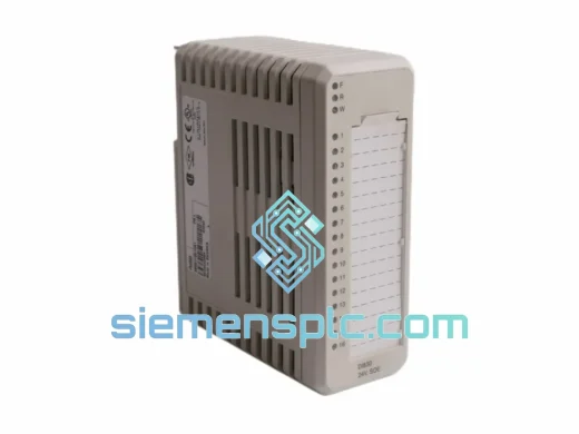
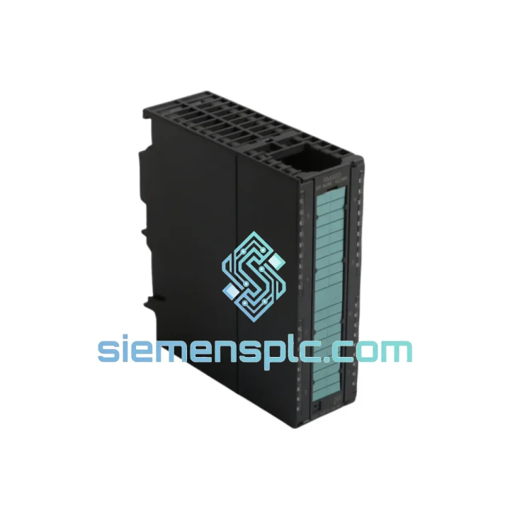
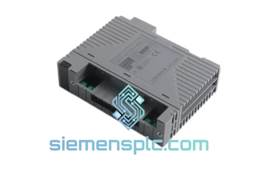
Siemens 6ES7322-1HF10-0AA0 Digital Output Module – SM322
Request verified availability, condition, replacement risk review, packing options and courier lead time for 6ES7322-1HF10-0AA0.
BrandSiemens
Part Number6ES7322-1HF10-0AA0
ConditionAvailability Check
Lead TimeRFQ Confirmation
DocumentsDatasheet / photos by RFQ
ShippingExport packing available
Auto-filled RFQ
6ES7322-1HF10-0AA0
Click Request Quote and the part number is inserted into the inquiry form automatically.
- Reply by email: [email protected]
- WhatsApp / Tel: +86 18359268345
- Mon-Sat 9:00-18:00 GMT+8
Procurement Data
Key Product Information
Core fields for model confirmation and RFQ routing. Detailed product narrative remains below.
- Brand
- Siemens
- Primary Part Number
- 6ES7322-1HF10-0AA0
- Product Type
- PLC Digital Output Module
- Series / Family
- SIMATIC S7-300
- Country of Origin
- DE
- Catalog Category
- I/O Modules
- Operating Temp.
- 0 °C to +60 °C (horizontal mounting); 0 °C to +40 °C (vertical)
- Warranty
- 12 months from date of shipment
Model confirmed for inquiry
6ES7322-1HF10-0AA0
Send quantity, destination and urgency. The RFQ form keeps this part number attached.
Request Quote
Product Overview
Siemens 6ES7322-1HF10-0AA0 — 8-Channel DC 24V Transistor Output Module for SIMATIC S7-300 Control Systems
The 6ES7322-1HF10-0AA0 is a member of the SM322 signal module family within the SIMATIC S7-300 distributed control architecture. It delivers eight sourcing transistor output channels rated at DC 24 V / 2 A per channel, with a cumulative module current ceiling of 8 A. Designed for deterministic discrete output control, this module occupies a single slot on any S7-300 backplane rack and communicates with the CPU via the proprietary P-bus (peripheral bus) at a cycle-synchronous update rate. Its compact 40 mm width allows high-density rack configurations without compromising per-channel drive capacity — a balance that distinguishes it from the 16-channel 0.5 A variants in the same SM322 family.
In a typical S7-300 control loop, the CPU writes output image data to the process image output (PIO) table at the end of each OB1 scan cycle. The SM322 module reads this image data from the backplane bus and drives the corresponding transistor output stages within one bus cycle — typically under 1 ms for standard rack configurations. This deterministic latency makes the 6ES7322-1HF10-0AA0 suitable for time-critical discrete actuator control, including solenoid valve sequencing in pneumatic manifolds, contactor switching in motor control centers, and signal lamp driving on operator panels.
Real-time Stock & RFQ: [email protected] | WhatsApp: +86 18359268345
Technical Parameters
| Parameter | Value |
|---|---|
| Order Number (MLFB) | 6ES7322-1HF10-0AA0 |
| Module Series | SM322 — Signal Module, Digital Output |
| PLC Platform | SIMATIC S7-300 |
| Number of Output Channels | 8 |
| Output Type | Transistor, sourcing (PNP) |
| Rated Output Voltage | DC 24 V (range: 20.4 V – 28.8 V) |
| Rated Output Current per Channel | 2 A |
| Maximum Module Current | 8 A |
| Isolation Method | Optocoupler (field side vs. backplane bus) |
| Short-Circuit Protection | Electronic, per channel |
| Backplane Bus Current (5 V DC) | 80 mA |
| Load Voltage Supply Current (24 V) | Max. 100 mA (module internal) |
| Power Dissipation | Approx. 4.5 W at full load |
| Output Switching Frequency (resistive load) | 100 Hz |
| Output Switching Frequency (inductive load) | 0.5 Hz |
| Residual Current (output OFF) | ≤ 0.5 mA |
| Signal Delay (0→1) | ≤ 0.5 ms |
| Signal Delay (1→0) | ≤ 1.5 ms |
| Dimensions (W × H × D) | 40 × 125 × 120 mm |
| Weight | Approx. 320 g |
| Operating Temperature | 0 °C to +60 °C (horizontal mounting); 0 °C to +40 °C (vertical) |
| Storage Temperature | −40 °C to +70 °C |
| Relative Humidity | 10% – 95%, non-condensing |
| Degree of Protection | IP20 |
| Front Connector | 20-pin (order separately: 6ES7392-1AJ00-0AA0) |
| Certifications | CE, UL, cULus, FM, ATEX (Zone 2) |
| Warranty | 12 months from date of shipment |
Hardware Logical Analysis
Optocoupler Isolation Architecture: Each of the eight output channels is galvanically isolated from the S7-300 backplane bus via a dedicated optocoupler stage. The LED side of the optocoupler is driven by the backplane bus logic (5 V domain), while the phototransistor side interfaces with the 24 V field supply. This arrangement provides a minimum isolation voltage of 500 V AC (1 min test), preventing ground loops and transient voltage spikes originating from inductive field loads from propagating into the CPU’s logic domain. In environments with variable-frequency drives (VFDs) or large contactors, this isolation barrier is the primary defense against common-mode noise injection.
Transistor Output Stage and Electronic Short-Circuit Protection: The output transistors are configured in a high-side (sourcing) topology, meaning the load is connected between the output terminal and the 0 V reference. Each channel incorporates an integrated current-limiting circuit that activates when the output current exceeds approximately 3 A (typical trip threshold). Upon detection, the transistor is switched off within microseconds, and the fault state is latched until the CPU clears it via a write cycle. This electronic protection eliminates the need for external fusing on individual output channels in most standard load configurations, reducing panel wiring complexity.
Backplane Bus Interface and Process Image Synchronization: The module interfaces with the S7-300 P-bus through a dedicated ASIC that handles address decoding, data latching, and bus arbitration. Output data is transferred from the CPU’s process image output (PIO) to the module’s output latch register at the end of each OB1 scan cycle (or at the configured I/O update point in interrupt-driven OBs). The latch register holds the last valid output state independently of bus activity, ensuring that output channels remain stable during bus communication gaps — a critical behavior for solenoid valve control where unintended de-energization could cause process upsets.
EMC Design and Conducted Emission Suppression: The module’s PCB layout employs a split ground plane strategy: the 5 V logic ground and the 24 V field ground are separated and connected only at a single star point near the backplane connector. This minimizes high-frequency return current coupling between the logic and field domains. Ferrite beads are placed on the 24 V supply lines entering the module to attenuate conducted emissions above 1 MHz, in compliance with EN 61000-6-4 (industrial emission standard). The module is tested to EN 61000-4-4 (electrical fast transient / burst) at 2 kV on the power supply lines and 1 kV on signal lines.
Thermal Management: At maximum load (8 A total, 4.5 W dissipation), the module relies on natural convection cooling within the control cabinet. The 40 mm slot width provides adequate airflow clearance when modules are mounted in standard S7-300 racks. Siemens specifies a derating curve for ambient temperatures above 40 °C in vertical mounting orientation — at 60 °C, the total module current must be reduced to maintain junction temperatures within the transistor’s safe operating area.
System Integration Benefits
- Direct S7-300 Backplane Compatibility: The module slots into any UR1, UR2, ER1, or ER2 rack without adapter hardware. Address assignment is automatic via STEP 7 or TIA Portal hardware configuration, eliminating manual DIP switch settings and reducing commissioning time.
- 2 A Per-Channel Drive Capacity: Supports direct switching of 24 V DC solenoid valves (typically 0.5–1.5 A inrush), contactors up to IEC utilization category AC-15, and high-brightness indicator lamps without external relay interposing — reducing BOM cost and panel footprint.
- Electronic Short-Circuit Protection with CPU Feedback: Fault states are readable via the module’s diagnostic byte in the process image input (PII), allowing the CPU program to implement structured fault handling routines (e.g., alarm generation, safe-state activation) without requiring external monitoring relays.
- Sub-millisecond Output Update Latency: With a 0→1 signal delay of ≤ 0.5 ms, the module supports time-critical sequencing applications such as pneumatic valve timing in high-speed packaging lines where actuator response windows are in the 5–20 ms range.
- Galvanic Isolation Eliminates Ground Loop Interference: In multi-panel installations where field devices and the PLC cabinet share different ground references, the 500 V isolation barrier prevents circulating ground currents from corrupting output signal integrity — a common failure mode in large-scale process plants.
- Consistent Output State During CPU Stop Mode: The output latch retains its last state during CPU STOP transitions (configurable via hardware configuration), allowing process engineers to define a defined safe output state (all OFF or last value) without additional external logic.
- TIA Portal and STEP 7 Full Software Support: The module is fully parameterizable within SIMATIC STEP 7 V5.x and TIA Portal V13 and above. Diagnostic information, including short-circuit flags and supply voltage monitoring, is accessible via standard SFB/SFC calls, enabling integration into existing plant-level SCADA diagnostic frameworks.
- Scalable Architecture for Expansion: The S7-300 platform supports up to 32 modules per CPU (across central and expansion racks), allowing the 6ES7322-1HF10-0AA0 to be deployed in multi-rack configurations for large discrete output counts without changing the programming model or communication protocol.
- Compact 40 mm Width Maximizes Rack Density: Compared to relay output modules of equivalent channel count, the transistor-based SM322 occupies the minimum slot width in the S7-300 form factor, allowing up to 8 modules per rack and maximizing I/O density in space-constrained control cabinets.
- Long-Term Spare Parts Availability: The S7-300 platform has an established global spare parts ecosystem. The 6ES7322-1HF10-0AA0 remains available through authorized Siemens distribution channels, ensuring long-term maintainability for installed base systems with 10–20 year operational lifespans.
Quality Assurance & Global Logistics
Every 6ES7322-1HF10-0AA0 unit supplied through siemensplc.com is sourced as genuine Siemens original hardware. Each module carries the factory MLFB label with full traceability to Siemens’ manufacturing batch records. Prior to shipment from our Xiamen, China facility, each unit undergoes a structured pre-shipment inspection protocol:
- Label and MLFB Verification: The order number, firmware revision, and date code are cross-checked against Siemens’ published MLFB coding structure to confirm authenticity.
- Power-On Functional Test: Each module is energized on a test rack with a compatible S7-300 CPU. All eight output channels are exercised through a full ON/OFF cycle under a resistive test load to verify switching function and short-circuit protection response.
- Visual and Mechanical Inspection: Connector pins, front panel labeling, and housing integrity are inspected to IPC-A-610 Class 2 workmanship standards.
- ESD-Safe Packaging: Modules are packed in anti-static bags with humidity indicator cards, placed in foam-lined cartons rated for international air freight handling (ISTA 2A drop test equivalent).
- 12-Month Warranty: All units carry a 12-month warranty from the date of shipment, covering manufacturing defects and functional failures under normal operating conditions.
Logistics from Xiamen, China to global destinations are handled via DHL Express, FedEx International Priority, and UPS Worldwide Express. Standard transit times are 3–5 business days to Europe and North America, 2–4 business days to Southeast Asia and the Middle East. For bulk orders, sea freight consolidation via Xiamen Port is available with typical transit times of 18–25 days to European ports. All shipments include commercial invoice, packing list, and certificate of conformity. Export classification: HS Code 8537.10 (boards, panels, consoles for electric control).
Contact Information
Email: [email protected]
WhatsApp: +86 18359268345
Web: siemensplc.com
Location: Xiamen, China
© 2026 siemensplc.com. All rights reserved.
Ready to quote
[email protected]
Send This Part Number to Sales
RFQ workflow
Quality workflow ->
Confirmation Process
01Model confirmation
We check the full part number, brand, series and visible nameplate information before quotation.
02Availability reply
Sales confirms stock path, condition option, quantity and realistic lead time for export dispatch.
03Packing & courier
DHL, FedEx, UPS or buyer courier arrangements can be reviewed with packing requirements.
Continue sourcing
Browse full catalog ->
Related Automation Parts
Similar brand or category products for fast comparison and multi-item RFQ lists.
Siemens
RFQ Ready
Siemens 6ES7 315-2EH14-0AB0 CPU 315-2 PN/DP Module
SIMATIC S7-300
Origin DE
PLC CPU Module
Siemens
RFQ Ready
Siemens 6ES7315-2EH14-0AB0 CPU 315-2 PN/DP PLC Module
SIMATIC S7-300
Origin DE
PLC CPU Module
Siemens
RFQ Ready
Siemens 6ES7 321-1BL00-0AA0 Digital Input Module
SIMATIC S7-300
Origin DE
PLC Digital Input Module