Siemens
RFQ Ready
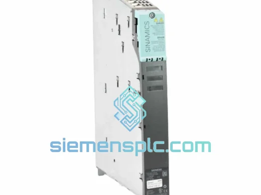
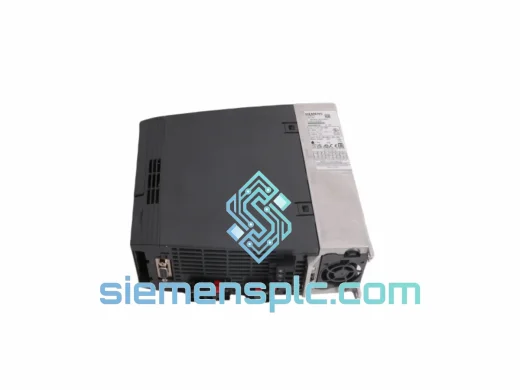
Siemens 6SL3210-1KE18-8UP1 AC Drive Power Module
SINAMICS
Origin DE
AC Drive Power Module
Request verified availability, condition, replacement risk review, packing options and courier lead time for ULC0186 A5E00182136.
Click Request Quote and the part number is inserted into the inquiry form automatically.
Core fields for model confirmation and RFQ routing. Detailed product narrative remains below.
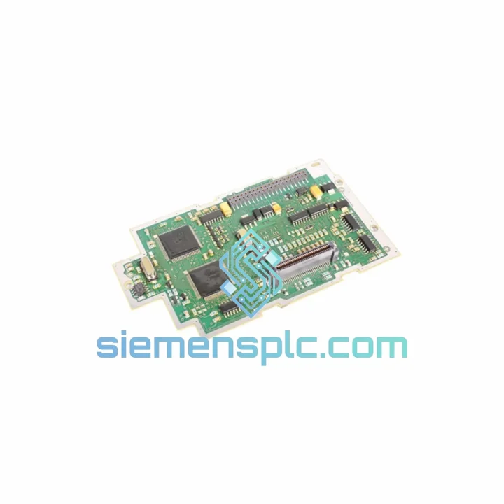
The Siemens ULC0186 (order reference A5E00182136) is the primary drive control printed circuit board deployed within the Siemens SINAMICS and MICROMASTER variable-frequency drive families. Its function is not peripheral — it sits at the intersection of power electronics and digital control logic, translating high-level speed and torque commands into precisely timed IGBT gate pulses while simultaneously processing encoder feedback, current sensor signals, and thermal monitoring data. When this board fails, the inverter loses its ability to modulate output voltage and frequency, resulting in immediate drive fault and motor shutdown.
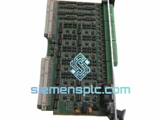
The MICROMASTER 4 series (MM420, MM430, MM440) and the early SINAMICS G-series platforms share a common hardware lineage in their control board architecture. The ULC0186 A5E00182136 represents the Siemens engineering standard for this generation: a multi-layer PCB with dedicated analog front-end circuitry for current and voltage sensing, a DSP-based control core executing the field-oriented control (FOC) algorithm, and isolated gate driver stages for each IGBT phase leg. Understanding this architecture is essential for maintenance engineers selecting a verified replacement.
Real-time Stock & RFQ: [email protected] | WhatsApp: +86 18359268345
| Parameter | Specification |
|---|---|
| Part Number | ULC0186 |
| Siemens Order Number | A5E00182136 |
| Component Classification | PCB Drive Control Board (Gate Driver + DSP Control) |
| Compatible Drive Series | Siemens MICROMASTER 4 (MM420 / MM430 / MM440), SINAMICS G-series (selected variants) |
| Control Topology | Field-Oriented Control (FOC) / V/f open-loop selectable |
| Gate Signal Output | 6-channel isolated IGBT gate drive (3-phase bridge) |
| Feedback Inputs | Analog current sensors (3-phase), DC bus voltage divider, NTC thermal input |
| Communication Interface | PROFIBUS DP (optional module slot), USS protocol via RS-485 |
| Logic Supply Voltage | +5 VDC / ±15 VDC (derived from internal SMPS) |
| Operating Temperature | –10 °C to +50 °C (ambient, drive enclosure) |
| PCB Construction | Multi-layer FR4, conformal coating on production variants |
| Weight (board only) | Approx. 100 g |
| Manufacturer | Siemens AG, Germany |
| Warranty | 12 months from date of shipment |
The ULC0186 A5E00182136 integrates three distinct functional blocks on a single PCB, each with its own signal domain and isolation boundary.
1. Analog Signal Conditioning Front-End: Three Hall-effect current transducers feed differential signals into a precision instrumentation amplifier stage on the board. These signals are anti-alias filtered at approximately 10 kHz before entering the ADC inputs of the DSP. The DC bus voltage is sampled through a resistive divider network with a dedicated buffer amplifier, providing the control loop with real-time intermediate circuit voltage data. This architecture allows the FOC algorithm to compensate for DC bus ripple in real time — a critical requirement in drives operating from unregulated rectifier supplies.
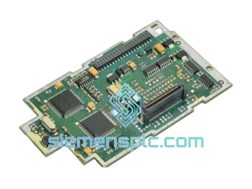
2. DSP Control Core and PWM Generation: The central processor executes the space-vector PWM (SVPWM) modulation algorithm at a carrier frequency selectable between 2 kHz and 16 kHz (drive-model dependent). The dead-time insertion logic — implemented in hardware to prevent shoot-through in the IGBT bridge — is fixed at the silicon level, not in firmware, ensuring deterministic switching behavior regardless of software state. This is a deliberate Siemens design choice that eliminates a class of firmware-induced fault conditions seen in competing architectures.
3. Isolated Gate Driver Stage: Each of the six IGBT gate channels is driven through a transformer-isolated gate driver IC. The isolation barrier sustains a minimum of 1,500 Vrms continuous, with a common-mode transient immunity (CMTI) rating exceeding 50 kV/µs — sufficient to reject the dV/dt transients generated by modern fast-switching IGBTs. The gate resistors are sized per Siemens thermal and EMC specifications, balancing switching loss against conducted EMI generation.
4. EMC Design: The board layout follows Siemens internal EMC guidelines: analog and digital ground planes are separated and joined at a single star point, high-frequency decoupling capacitors are placed within 2 mm of each IC power pin, and the gate drive traces are routed as controlled-impedance pairs. These measures ensure the board meets EN 61800-3 Category C2 conducted and radiated emission limits when installed in a compliant drive enclosure.
Every ULC0186 A5E00182136 unit dispatched from our Xiamen, China facility is a genuine Siemens-manufactured component. Siemens AG produces these boards under ISO 9001-certified manufacturing processes, with component traceability maintained from wafer-level semiconductor sourcing through final board assembly and functional test. The Siemens order number A5E00182136 is the definitive identifier for this board revision — any unit bearing this number has been manufactured to the same electrical and mechanical specification as the original equipment installation.
Our pre-shipment verification process includes: visual inspection under 10× magnification for solder joint integrity and PCB trace condition; part number and revision code cross-check against Siemens documentation; and where stock condition permits, a powered bench verification confirming logic supply rails and gate driver output signals. Units are packed in anti-static (ESD) shielding bags, placed in foam-lined cartons, and outer-packed in double-wall corrugated boxes rated for international air freight handling.
Shipments originate from Xiamen, China, with DHL Express, FedEx International Priority, and UPS Worldwide Express available as carrier options. Transit times to major industrial hubs: Europe 3–5 business days, North America 4–6 business days, Southeast Asia 2–3 business days, Middle East 4–7 business days. Full commercial invoice, packing list, and certificate of origin are provided with every shipment to facilitate customs clearance. HS code 8538.90 applies to this component category for most jurisdictions. All units are covered by a 12-month warranty from the date of shipment.
Email: [email protected]
WhatsApp: +86 18359268345
Web: siemensplc.com
Location: Xiamen, China
© 2026 siemensplc.com. All rights reserved.
We check the full part number, brand, series and visible nameplate information before quotation.
Sales confirms stock path, condition option, quantity and realistic lead time for export dispatch.
DHL, FedEx, UPS or buyer courier arrangements can be reviewed with packing requirements.
Similar brand or category products for fast comparison and multi-item RFQ lists.