Reliance Electric
RFQ Ready
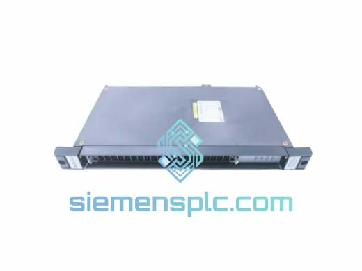
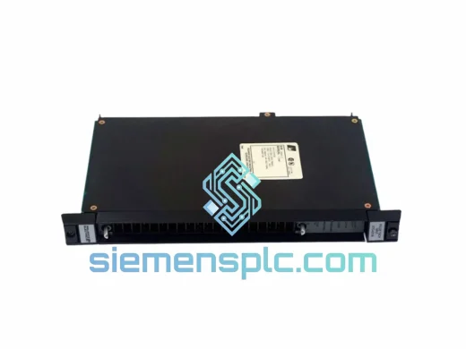
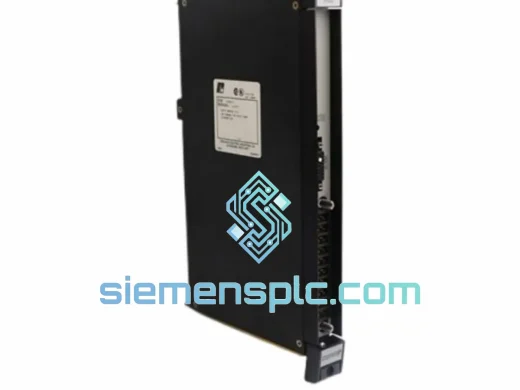
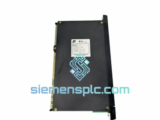
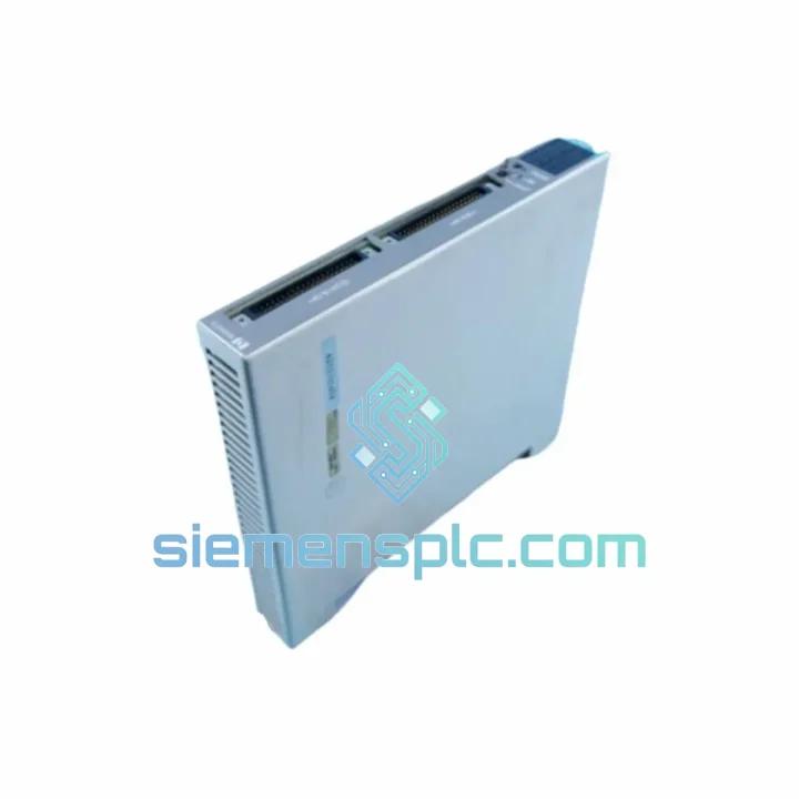
Reliance Electric 57C420 Digital Output Module
AutoMax
Origin US
Digital Output Module
Request verified availability, condition, replacement risk review, packing options and courier lead time for S-D4006-D.
Click Request Quote and the part number is inserted into the inquiry form automatically.
Core fields for model confirmation and RFQ routing. Detailed product narrative remains below.
The RELIANCE Electric S-D4006-D (alternate part reference: S-D4006) is a single-slot discrete digital input/output module engineered specifically for the S-D4000 modular drive control platform. Its primary function within a closed-loop drive system is to extend the host CPU’s discrete signal capacity while maintaining the bounded, deterministic scan-cycle timing that torque regulation, axis positioning, and safety interlock logic demand. Unlike general-purpose I/O cards adapted for drive environments, the S-D4006-D is architected from the ground up to operate as a native peripheral on the S-D4000 backplane’s synchronous time-division multiplexed (TDM) communication bus.
In practical terms, this means the module does not poll or negotiate bus access. The S-D4000 CPU assigns each populated slot a fixed time slot within its scan cycle at power-up enumeration. The S-D4006-D’s channel states — both inputs sampled from field devices and outputs commanded by the application program — are transferred within that fixed window on every scan, regardless of how many other modules occupy the rack. The result is a worst-case input-to-output latency that is a deterministic engineering parameter, not a probabilistic estimate. For control engineers specifying discrete I/O for conveyor indexing, press brake control, or multi-axis positioning systems where interlock response time tolerances are measured in single-digit milliseconds, this determinism is a functional requirement, not a preference.
Field-side connectivity covers the full range of 24 VDC discrete devices encountered in motor drive panels: two-wire inductive proximity sensors, three-wire PNP and NPN proximity sensors, photoelectric sensors with push-pull outputs, mechanical limit switches, solenoid valve coils, motor starter auxiliary contacts, and relay coils. No external signal conditioning hardware, interposing relays, or pull-up resistor networks are required for standard wiring configurations, which reduces panel wiring complexity, lowers BOM cost, and eliminates a category of field wiring errors that manifest as intermittent faults under vibration.
Real-time Stock & RFQ: [email protected] | WhatsApp: +86 18359268345
| Parameter | Specification |
|---|---|
| Part Number | S-D4006-D (cross-ref: S-D4006) |
| Manufacturer | RELIANCE Electric |
| Platform Series | S-D4000 Modular Drive Control |
| Module Function | Discrete Digital Input / Output (mixed) |
| Field-Side Nominal Voltage | 24 VDC |
| Input ON Threshold | ≥ 15 VDC (typical) |
| Input OFF Threshold | ≤ 5 VDC (typical) |
| Input Current Draw (per channel, ON) | ≈ 7 mA at 24 VDC nominal |
| Output Stage Technology | Solid-state DC (MOSFET/Darlington); no mechanical contacts |
| Isolation Architecture | Per-channel photocoupler, field-to-logic galvanic isolation |
| Transient Suppression Rating | Rated for inductive spike suppression ≥ 500 VDC, < 500 ns rise time |
| Backplane Interface | S-D4000 proprietary synchronous TDM bus |
| Slot Address Assignment | Automatic enumeration at power-up; no DIP switch required |
| Form Factor | Single-slot, S-D4000 rack, gold-plated card-edge connector |
| Operating Temperature | 0 °C to +55 °C (panel-mounted, still-air ambient) |
| Storage Temperature | −25 °C to +70 °C |
| Relative Humidity | 5% to 95%, non-condensing |
| Module Weight | 1,380 g (approx. 3.04 lb) |
| Certifications | UL Listed; CE Mark (OEM original) |
| Warranty | 12 months from confirmed shipment date |
The S-D4006-D’s isolation topology places a discrete photocoupler at the boundary of every channel — input and output alike. On the input side, the field signal drives the LED emitter of the photocoupler through a precision current-limiting resistor network calibrated for 24 VDC nominal operation. The phototransistor on the logic side responds to the optical signal with no galvanic path between the field conductor and the module’s internal logic rail. This architecture provides common-mode rejection sufficient to absorb inductive transients generated by contactor coil de-energization and solenoid switching — events that routinely produce voltage spikes of 200–600 VDC with sub-500 ns rise times in motor drive enclosures. These transients are blocked at the photocoupler boundary and cannot propagate to the S-D4000 backplane bus, where they would otherwise corrupt TDM data frames or latch up logic ICs on adjacent modules.
The DC output stage uses solid-state switching elements — power MOSFETs or Darlington-configured bipolar transistors depending on channel group — rather than mechanical relay contacts. This eliminates three failure modes inherent to relay-based outputs: contact bounce during switching transients, contact welding under inrush current from capacitive or inductive loads, and mechanical wear that limits relay contacts to a finite switching cycle count. In high-cycle applications — conveyor indexing, packaging machinery, press control — where output channels may execute 10,000 to 50,000 switching events per shift, the solid-state output stage extends the module’s service interval by two to three orders of magnitude compared to relay alternatives, with no scheduled contact replacement required.
PCB-level EMC design addresses the noise environment of a PWM motor drive panel through deliberate ground plane segmentation. The field-side return conductors and the logic-side ground plane are physically separated on the PCB substrate, with the photocoupler forming the sole signal path across the isolation boundary. This prevents high-frequency noise currents — particularly those generated by PWM inverters operating at switching frequencies of 2 kHz to 16 kHz — from coupling into the backplane bus through shared ground impedance. Distributed ceramic decoupling capacitors placed at each logic IC power supply pin attenuate supply-rail noise in the frequency bands most relevant to PWM-generated interference, maintaining logic voltage margins within datasheet specification under worst-case simultaneous multi-axis drive operation.
The card-edge connector uses gold-plated contacts to maintain low, stable contact resistance across the module’s service life in industrial atmospheric conditions. Gold plating resists the formation of resistive oxide films that develop on tin or silver contacts exposed to moderate humidity, sulfur compounds, or industrial particulate contamination. The connector geometry is mechanically keyed to prevent insertion into an incompatible slot type, eliminating the risk of backplane bus contention or power supply damage caused by module misplacement during maintenance. Front-panel LED indicators — one per channel — display the logical state as interpreted by the module’s internal logic, not the raw field-side voltage level. This distinction is diagnostically significant: an illuminated output indicator with no field-side response isolates the fault to the external wiring or load device; an unlit indicator with confirmed field-side voltage present isolates the fault to the module itself, compressing fault localization from hours to minutes in production environments where downtime cost is measured per minute of lost output.
Every S-D4006-D unit dispatched from our Xiamen, China facility passes a structured pre-shipment inspection sequence before packaging. Visual inspection covers PCB surface condition, solder joint integrity at all through-hole and surface-mount joints, card-edge connector contact plating condition, and front-panel indicator lens integrity. Functional verification applies calibrated 24 VDC input signals to each channel in sequence and confirms correct logical state reporting through the backplane interface using a dedicated test fixture that replicates the S-D4000 backplane electrical environment. Units held in warehouse storage for extended periods undergo a voltage burn-in period under nominal operating conditions to screen for latent component failures — particularly electrolytic capacitor parameter drift and solder joint fatigue — before dispatch.
Packaging uses anti-static ESD shielding bags with humidity indicator cards, placed within foam-lined corrugated cartons dimensioned to prevent module movement during air freight handling. Outer carton labeling includes part number, serial number, and handling instructions in English. Export documentation — commercial invoice, packing list, certificate of origin, and where required, export control classification documentation — is prepared to comply with customs clearance requirements in the destination country, minimizing customs broker processing time for international shipments.
Primary logistics partners are DHL Express, FedEx International Priority, and UPS Worldwide Express, with typical transit times of 3–5 business days to destinations in North America, Western Europe, and Southeast Asia. For urgent unplanned replacement requirements, same-day dispatch is available for confirmed in-stock units when orders are confirmed before the daily cut-off time. Full shipment tracking references are provided at the time of dispatch, with proactive status updates for shipments to destinations with complex customs processing environments.
The 12-month warranty covers functional defects attributable to the module under normal operating conditions as defined in the original RELIANCE Electric product documentation. Warranty claims are acknowledged within 24 hours of receipt and processed with a target resolution time of 48 hours from receipt of the defective unit at our Xiamen facility.
Email: [email protected]
WhatsApp: +86 18359268345
Web: siemensplc.com
Location: Xiamen, China
© 2026 siemensplc.com. All rights reserved.
We check the full part number, brand, series and visible nameplate information before quotation.
Sales confirms stock path, condition option, quantity and realistic lead time for export dispatch.
DHL, FedEx, UPS or buyer courier arrangements can be reviewed with packing requirements.
Similar brand or category products for fast comparison and multi-item RFQ lists.