ABB
RFQ Ready
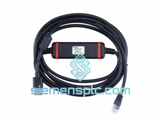
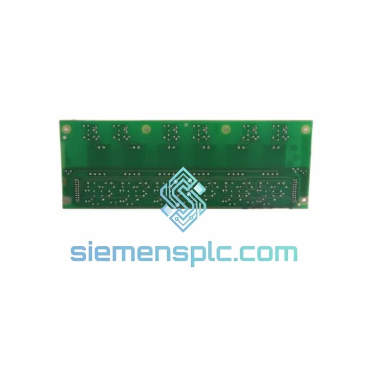
ABB NPCU-01 Drive Communication Cable – ACS Series
ACS Drive
Origin SE
Drive Communication Accessory
Request verified availability, condition, replacement risk review, packing options and courier lead time for ZINT-592.
Click Request Quote and the part number is inserted into the inquiry form automatically.
Core fields for model confirmation and RFQ routing. Detailed product narrative remains below.
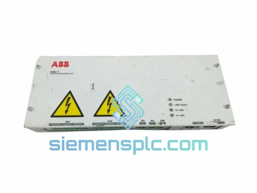
The ABB ZINT-592 is a plug-in option board engineered for direct installation into ABB ACS-series variable frequency drives (VFDs), specifically the ACS550 and ACS800 platforms. Its primary function is to extend the drive’s native control architecture with a standardized fieldbus communication layer, enabling deterministic, cyclic data exchange between the drive and an upstream PLC, DCS, or SCADA master. In process-critical environments where analog speed references and discrete I/O wiring introduce latency, noise susceptibility, and limited diagnostic visibility, the ZINT-592 replaces that wiring infrastructure with a single, shielded fieldbus cable carrying both control and status data at defined scan cycle intervals.
The board occupies the drive’s dedicated option slot, interfacing directly with the drive’s internal communication bus. This architecture eliminates the need for external signal converters or gateway hardware between the fieldbus network and the drive’s parameter space. Once installed and configured, the PLC master can read and write drive parameters — including speed reference, torque limit, control word, and status word — within the same network scan cycle used for all other field devices on the segment.
Real-time Stock & RFQ: [email protected] | WhatsApp: +86 18359268345
| Parameter | Specification |
|---|---|
| Manufacturer | ABB |
| Part Number / SKU | ZINT-592 |
| Product Category | Fieldbus Communication Interface Board |
| Compatible Drive Platforms | ABB ACS550, ACS800 |
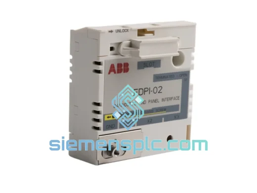
| Mounting Interface | Drive option slot (direct plug-in, no external wiring) |
| Communication Function | Cyclic fieldbus data exchange — control word, speed ref, status word, actual values |
| Operating Ambient Temperature | −10 °C to +55 °C (within drive enclosure) |
| Storage Temperature | −40 °C to +70 °C |
| Relative Humidity | 5–95% RH, non-condensing |
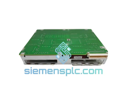
| PCB Construction | Industrial-grade, conformal-coat eligible |
| Compliance | CE (LVD + EMC Directive), RoHS, IEC 61800-3, IEC 61158 |
| Weight | 268 g |
| Country of Origin | Finland (ABB standard manufacturing) |
| Warranty | 12 months from date of dispatch |
The ZINT-592 operates as a subordinate node on the drive’s internal option bus, which runs at a fixed clock rate synchronized to the drive’s main control board firmware cycle. This synchronization is architecturally significant: the interface board does not buffer fieldbus telegrams asynchronously and then forward them to the drive at an arbitrary time. Instead, the drive’s control task reads the latest fieldbus-received reference values at the start of each control cycle, ensuring that the speed or torque reference applied to the motor control algorithm is never more than one control cycle old relative to the fieldbus telegram receipt timestamp.
From an EMC standpoint, the board’s signal traces are routed with controlled impedance to minimize reflections on the fieldbus physical layer. The option slot connector provides a ground reference plane shared with the drive’s main control board, which is itself bonded to the drive’s PE (protective earth) rail. This common ground architecture reduces common-mode noise coupling between the fieldbus cable shield and the drive’s internal logic circuitry — a failure mode that frequently causes intermittent communication faults in installations where the interface board and drive share a noisy industrial power environment.
The board’s power supply is derived entirely from the drive’s internal 5 VDC and 3.3 VDC rails via the option slot connector. No external auxiliary supply is required, which eliminates a potential single-point-of-failure in the communication path. The onboard voltage regulation circuitry includes transient suppression components rated for the inductive switching environment typical of a VFD enclosure, where dV/dt events on the DC bus can couple into logic supply rails through parasitic capacitance.
Termination resistor management is handled at the network level rather than on the board itself, consistent with the fieldbus physical layer standard. End-of-line nodes on the segment must have termination applied at the cable connector, not at the board. This design keeps the board’s footprint minimal and avoids the reliability issues associated with on-board switchable termination components that can fail in high-vibration installations.
Every ABB ZINT-592 unit dispatched from our Xiamen, China facility is sourced through verified industrial distribution channels and subjected to a structured pre-shipment inspection protocol. Visual examination covers PCB surface condition, connector pin integrity, component seating, and label authenticity cross-referenced against ABB OEM documentation. Part markings, date codes, and packaging are verified against known-good reference samples to identify non-genuine or remarked components before they enter the supply chain.
Units are packed in ESD-safe anti-static bags, placed in foam-padded inner cartons, and shipped in double-wall outer cartons rated for international air freight handling. For time-critical requirements, DHL Express and FedEx International Priority services from Xiamen Gaoqi International Airport provide transit times of 3–5 business days to most destinations in Europe, North America, Southeast Asia, and the Middle East. Sea freight consolidation is available for volume orders where lead time permits. Full export documentation — commercial invoice, packing list, certificate of origin, and HS code declaration — is prepared for every shipment to facilitate customs clearance without delay.
All units carry a 12-month warranty from the date of dispatch. Warranty claims are processed via email with photographic evidence of the defect; replacement units are dispatched within 3 business days of claim approval. Technical support for installation, parameter configuration, and fieldbus commissioning is available via email and WhatsApp throughout the warranty period and beyond.
Email: [email protected]
WhatsApp: +86 18359268345
Web: siemensplc.com
Location: Xiamen, China
© 2026 siemensplc.com. All rights reserved.
We check the full part number, brand, series and visible nameplate information before quotation.
Sales confirms stock path, condition option, quantity and realistic lead time for export dispatch.
DHL, FedEx, UPS or buyer courier arrangements can be reviewed with packing requirements.
Similar brand or category products for fast comparison and multi-item RFQ lists.