KUKA
In Stock OK
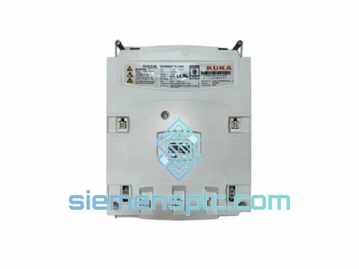
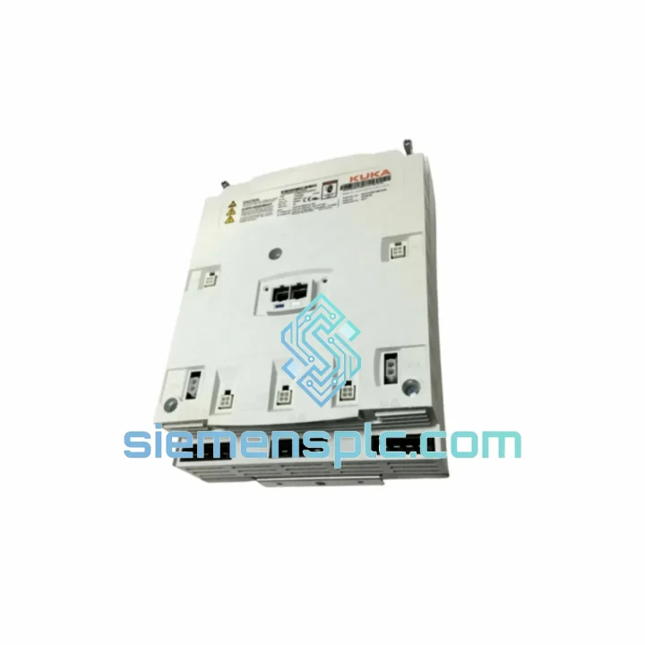
KUKA KPP 600-20 2X40 Controller Drive Power Supply – KR C4 Series
Request verified availability, condition, replacement risk review, packing options and courier lead time for 600-20.
BrandKUKA
Part Number600-20
ConditionAvailability Check
Lead TimeRFQ Confirmation
DocumentsDatasheet / photos by RFQ
ShippingExport packing available
Auto-filled RFQ
600-20
Click Request Quote and the part number is inserted into the inquiry form automatically.
- Reply by email: [email protected]
- WhatsApp / Tel: +86 18359268345
- Mon-Sat 9:00-18:00 GMT+8
Procurement Data
Key Product Information
Core fields for model confirmation and RFQ routing. Detailed product narrative remains below.
- Brand
- KUKA
- Primary Part Number
- 600-20
- Product Type
- Controller Drive Power Supply
- Product Family
- Other series
- Manufacturer
- KUKA Roboter GmbH, Augsburg, Germany
- Country of Origin
- DE
- Catalog Category
- PLCs & Controllers
- Warranty
- 12 months from date of shipment
Model confirmed for inquiry
600-20
Send quantity, destination and urgency. The RFQ form keeps this part number attached.
Request Quote
Product Overview
KUKA KPP 600-20 2X40 — DC Bus Power Architecture in KR C4 Multi-Axis Control Loops
The KUKA KPP 600-20 2X40 (Part No. 00-160-152) is the Controller Drive Power Supply module engineered for the KR C4 robot controller platform. Within the KR C4 cabinet’s power chain, this module occupies the upstream position: it rectifies incoming three-phase AC mains into a stabilized 600 V DC bus that feeds downstream KSD (KUKA Servo Drive) units. Each KSD axis draws regulated DC energy from this shared bus to execute torque commands issued by the KPC (KUKA Power Controller) over the EtherCAT-based KUKA System Bus (KSB). The 2X40 designation indicates dual-axis output capability at 40 A continuous per channel — a configuration suited to high-inertia axes such as A1 (base rotation) and A2 (shoulder) on KR 30 and KR 60 robot arms where peak regenerative braking currents can exceed 35 A during rapid deceleration cycles.
The module’s internal topology employs a six-pulse diode bridge rectifier followed by a DC link capacitor bank. During motor deceleration, kinetic energy is returned to the DC bus; when bus voltage exceeds the overvoltage threshold (nominally 750 V DC), the integrated ballast resistor circuit (chopper transistor + external braking resistor) dissipates excess energy as heat, preventing bus overvoltage faults (KUKA error E1292/E1293). This architecture eliminates the need for an external line regeneration unit in standard duty cycles, reducing cabinet footprint and BOM cost.
Real-time Stock & RFQ: [email protected] | WhatsApp: +86 18359268345
Technical Parameters
| Parameter | Value |
|---|---|
| Part Number | 00-160-152 |
| Model Designation | KPP 600-20 2X40 |
| Manufacturer | KUKA Roboter GmbH, Augsburg, Germany |
| Compatible Platform | KR C4, KR C4 Compact, KR C4 smallSize |
| Input Voltage | 3-phase AC 400 V / 480 V (±10%) |
| DC Bus Output Voltage | 600 V DC (nominal) |
| Overvoltage Threshold | 750 V DC (ballast activation) |
| Rated Continuous Output Current | 2 × 40 A per axis channel |
| Rectifier Topology | Six-pulse diode bridge + DC link capacitor bank |
| Braking Circuit | Integrated chopper transistor + external ballast resistor |
| Cooling Method | Forced air (integrated axial fan, 24 V DC) |
| Protection Class | IP20 (cabinet-mounted installation) |
| Operating Temperature | 0 °C to +45 °C ambient |
| Storage Temperature | −25 °C to +70 °C |
| Relative Humidity | 5 % to 95 %, non-condensing |
| Module Weight | Approx. 800 g |
| Certifications | CE (2006/42/EC Machinery Directive) |
| STO Compliance | IEC 62061 SIL 2 / ISO 13849-1 PLd (via SIB) |
| Warranty | 12 months from date of shipment |
Hardware Logical Analysis
The KPP 600-20 2X40 is designed around three hardware disciplines that distinguish it from generic industrial power supplies:
1. DC Bus Impedance Management. The DC link capacitor bank is sized to maintain bus voltage ripple below 5 V peak-to-peak under full dual-axis load switching at 8 kHz PWM frequency. Low bus impedance is critical: any voltage sag during simultaneous axis acceleration would cause KSD current limiting, introducing position lag errors detectable at the KPC level. The capacitor bank uses film-type capacitors rated for 105 °C continuous operation, providing a calculated MTBF exceeding 80,000 hours at 40 °C ambient — a key factor in minimizing unplanned downtime in 24/7 automotive production environments.
2. EMC Shielding Architecture. The module’s PCB layout separates high-frequency switching nodes (chopper transistor gate drive, fan PWM) from the analog monitoring circuits (bus voltage sense, thermal sensor) using a ground plane partition strategy. Input mains filtering employs a common-mode choke rated at 25 A continuous, attenuating conducted emissions to comply with EN 55011 Class A limits. This is particularly relevant in KR C4 cabinets installed adjacent to high-power welding inverters, where common-mode noise on the PE conductor can reach 50 V peak.
3. Thermal Derating and Fan Redundancy Logic. The KPC monitors the KPP’s NTC thermistor output via the KSB. If module temperature exceeds 70 °C, the KPC initiates a controlled current derating sequence — reducing axis peak current limits by 15 % per 5 °C increment — before triggering a hard fault at 85 °C. The integrated fan operates at fixed speed (no PWM throttling), ensuring maximum airflow at all times. Fan failure is detected via a tachometer feedback signal; loss of tachometer pulse triggers a KPC warning (not an immediate fault), giving maintenance personnel a predictive maintenance window before thermal shutdown occurs.
System Integration Benefits
- Deterministic DC Bus Stability: The six-pulse rectifier with capacitor bank maintains bus voltage within ±2 % of 600 V DC under dynamic load transitions, ensuring KSD current loop bandwidth is not compromised by supply-side disturbances.
- Transparent Fault Diagnostics: Bus overvoltage, undervoltage, and thermal events are mapped to specific KUKA error codes (E1290–E1295) visible in KUKA smartPAD and WorkVisual log files, enabling root-cause isolation without oscilloscope measurement.
- STO Integration via SIB: The KPP interfaces with the Safety Interface Board (SIB) to implement Safe Torque Off per IEC 62061 SIL 2. STO activation cuts gate drive signals to all KSD modules within 10 ms, meeting Category 3 / PLd stop requirements without mechanical braking.
- Drop-in Cabinet Compatibility: The 2X40 variant uses the same mechanical envelope and connector pinout as other KPP 600-20 variants, enabling swap-out without cabinet rewiring. Only WorkVisual project reconfiguration is required when changing between 2X40 and 3X20 variants.
- Regenerative Energy Handling: The internal ballast circuit handles regenerative energy from deceleration cycles up to the rated chopper power, eliminating the need for external braking resistor cabinets in standard duty-cycle applications and reducing installation cost.
- Predictive Maintenance Data: Fan tachometer and NTC thermistor data are accessible via KPC diagnostic registers, enabling integration with KUKA.Connect or third-party OPC-UA data collectors for condition-based maintenance scheduling.
- Multi-Robot Cell Scalability: In multi-robot cells where several KR C4 cabinets share a common AC distribution panel, the KPP’s input filter suppresses inter-cabinet conducted interference, maintaining signal integrity on shared PE and neutral conductors.
- Reduced Commissioning Time: Because the KPP is a plug-and-play OEM module, KUKA WorkVisual automatically detects the replacement unit via the KSB device scan, eliminating manual parameter entry and reducing commissioning time to under 30 minutes for a trained engineer.
Quality Assurance & Global Logistics
Every KUKA KPP 600-20 2X40 unit dispatched from our Xiamen, China facility undergoes a structured pre-shipment verification protocol. DC bus output voltage is measured under a resistive load bank at 50 % rated current; insulation resistance between the DC bus and PE is verified at 500 V DC (minimum 10 MΩ); fan tachometer signal continuity is confirmed; and the module’s serial number and production date code are recorded against the shipment documentation for full traceability.
Units are sourced exclusively from KUKA-authorized distribution channels or verified OEM pull inventory from decommissioned robot cells with documented service history. No remanufactured, counterfeit, or third-party substitute components are stocked or shipped. A 12-month warranty covers all units against manufacturing defects and latent component failures under normal operating conditions.
Logistics from Xiamen port to global destinations are handled via DHL Express, FedEx International Priority, and UPS Worldwide Expedited, with typical transit times of 3–5 business days to Europe and North America. Export documentation (commercial invoice, packing list, HS code 8537.10) is prepared in compliance with Chinese customs regulations and destination country import requirements. DDP, DAP, and EXW Incoterms are all supported. For urgent production-line recovery scenarios, same-day dispatch is available for orders confirmed before 14:00 CST.
Contact Information
Email: [email protected]
WhatsApp: +86 18359268345
Web: siemensplc.com
Location: Xiamen, China
© 2026 siemensplc.com. All rights reserved.
Ready to quote
[email protected]
Send This Part Number to Sales
RFQ workflow
Quality workflow ->
Confirmation Process
01Model confirmation
We check the full part number, brand, series and visible nameplate information before quotation.
02Availability reply
Sales confirms stock path, condition option, quantity and realistic lead time for export dispatch.
03Packing & courier
DHL, FedEx, UPS or buyer courier arrangements can be reviewed with packing requirements.
Continue sourcing
Browse full catalog ->
Related Automation Parts
Similar brand or category products for fast comparison and multi-item RFQ lists.
KUKA
RFQ Ready
KUKA KSP 600 3X4000-160-154 Servo Drive Module
KR C4 Replacement
Origin DE
Servo Drive Module
KUKA
RFQ Ready
KUKA KRC4RDC 00-200-655 Robot Drive Controller – KRC4 Series
KRC4 Series
Origin DE
Robot Drive Controller
KUKA
RFQ Ready
KUKA 00-291-556 00-130-547 00-163-784 Robot Controller – KR C2 Series
Origin DE
Robot Controller