KUKA
In Stock OK
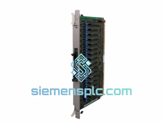
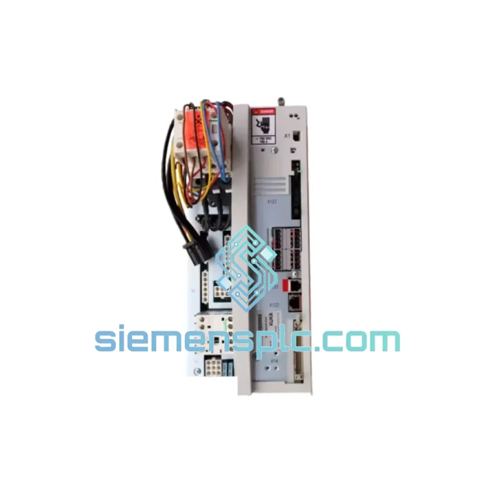
KUKA 00-198-266 KSP600-320 Servo Power Supply Unit – KRC4
Request verified availability, condition, replacement risk review, packing options and courier lead time for 00-198-266.
BrandKUKA
Part Number00-198-266
ConditionAvailability Check
Lead TimeRFQ Confirmation
DocumentsDatasheet / photos by RFQ
ShippingExport packing available
Auto-filled RFQ
00-198-266
Click Request Quote and the part number is inserted into the inquiry form automatically.
- Reply by email: [email protected]
- WhatsApp / Tel: +86 18359268345
- Mon-Sat 9:00-18:00 GMT+8
Procurement Data
Key Product Information
Core fields for model confirmation and RFQ routing. Detailed product narrative remains below.
- Brand
- KUKA
- Primary Part Number
- 00-198-266
- Product Type
- Servo Power Supply Unit
- Product Family
- Other series
- Manufacturer
- KUKA Roboter GmbH
- Country of Origin
- DE
- Catalog Category
- Industrial Automation Spares
- Warranty
- 12 months against manufacturing defects from date of dispatch
Model confirmed for inquiry
00-198-266
Send quantity, destination and urgency. The RFQ form keeps this part number attached.
Request Quote
Product Overview
KUKA 00-198-266 KSP600-320 — 600 V DC Servo Drive Power Supply for KRC4 Controller Cabinets
The KSP600-320 (KUKA part number 00-198-266) is the primary servo power supply module integrated into the KUKA KRC4 robot controller cabinet. Its function is singular and non-negotiable within the control architecture: it rectifies three-phase mains AC into a stabilised 600 V DC intermediate circuit that simultaneously energises all servo drive axes mounted on the KRC4 backplane. Every motion command issued by the KRC4 CPU — whether interpolated path segments, synchronised external axis movements, or SafeOperation-monitored velocity limits — depends on the DC bus maintained by this module. A degraded or failed KSP600-320 does not produce degraded motion; it produces a complete axis-enable fault and halts the entire kinematic chain.
This module is not a generic switch-mode power supply. It incorporates an active front-end (AFE) rectifier stage with power factor correction (PFC), a pre-charge circuit for controlled bus capacitor ramp-up, an integrated braking chopper for regenerative energy management, and a secondary 24 V DC SMPS rail that powers the KRC4 controller board, I/O modules, and the safety relay chain. Understanding each of these subsystems is essential for correct fault diagnosis and replacement qualification.
Real-time Stock & RFQ: [email protected] | WhatsApp: +86 18359268345
Technical Parameters
| Manufacturer | KUKA Roboter GmbH |
| Part Number | 00-198-266 |
| Module Designation | KSP600-320 |
| Compatible Controller | KUKA KRC4 (all variants incl. KRC4 compact, KRC4 smallsize) |
| DC Bus Output Voltage | 600 V DC (nominal), ±2% regulation under rated load |
| Continuous Output Current | 20 A |
| Peak Output Current | 320 A (designation suffix; burst capacity for simultaneous multi-axis acceleration) |
| Mains Input Voltage | 3-phase AC 400 V / 480 V, ±10% tolerance |
| Input Frequency | 50 Hz / 60 Hz |
| Power Factor | >0.95 at rated load (AFE PFC stage) |
| Secondary Logic Rail | 24 V DC, integrated SMPS; powers KRC4 controller board and I/O |
| Cooling Method | Forced-air convection via internal axial fan; thermally monitored |
| Protection Class | IP20 (cabinet-mounted, backplane-integrated) |
| Operating Temperature | 0 °C to +45 °C ambient |
| Storage Temperature | −25 °C to +70 °C |
| Relative Humidity | 5 % to 95 %, non-condensing |
| Mounting Interface | KRC4 cabinet backplane; proprietary KRC bus connector |
| Communication Interface | KRC internal EtherCAT-based servo bus (KRC4 generation) |
| Approvals | CE, UL (per KRC4 cabinet system certification) |
| Country of Origin | Germany |
| Warranty | 12 months against manufacturing defects from date of dispatch |
Hardware Logical Analysis
The KSP600-320 employs a three-stage power conversion architecture that distinguishes it from conventional passive rectifier PSUs found in earlier KUKA KRC2 cabinets.
Stage 1 — Active Front-End Rectifier with PFC: Rather than a simple diode bridge, the KSP600-320 uses a controlled IGBT bridge on the AC input side. This active rectifier draws near-sinusoidal current from the mains, achieving a power factor above 0.95 at rated load. The practical consequence for plant engineers is a reduction in harmonic distortion injected back into the facility supply — a meaningful consideration in dense robot installations where multiple KRC4 cabinets share a common distribution panel. The PFC stage also enables bidirectional energy flow, which is the prerequisite for the regenerative braking function described below.
Stage 2 — Pre-Charge and Bus Capacitor Management: On power-up, the 600 V DC bus capacitor bank (distributed across the KSP and individual KSD servo drive modules) presents a near-short-circuit load to the rectifier. The KSP600-320 incorporates a resistor-based pre-charge circuit that limits inrush current to a controlled ramp. Once bus voltage reaches approximately 90 % of nominal (≈540 V DC), the pre-charge relay bypasses the resistor and the main contactor closes. This sequence is monitored by the KRC4 controller; a failure to reach bus threshold within the defined time window generates a specific KRC fault code, enabling rapid isolation of the PSU versus a downstream capacitor fault.
Stage 3 — Regenerative Braking Chopper: During deceleration of high-inertia loads — common in automotive press-tending or palletising applications — the servo motors operate as generators, feeding energy back into the 600 V DC bus. The KSP600-320’s AFE stage can return this regenerated energy to the mains AC supply rather than dissipating it as heat through a braking resistor. This reduces thermal load inside the cabinet and lowers net energy consumption. In installations where regenerative return is not permitted by the local grid operator, an external braking resistor can be connected to the bus; the KSP600-320 includes the chopper transistor and gate-drive circuitry for this configuration.
EMC Design: The module’s AC input is preceded by a multi-stage LC filter integrated into the KRC4 cabinet’s mains entry panel. The KSP600-320 itself includes common-mode chokes on the DC bus output rails to suppress high-frequency switching noise from propagating to the servo drive modules. The cabinet backplane provides a low-impedance ground reference plane; the KSP600-320’s chassis is bonded directly to this plane, ensuring that EMC compliance of the overall KRC4 system is maintained even in environments with significant conducted interference (e.g., adjacent welding inverters operating at 50–100 kHz switching frequencies).
Thermal Monitoring and Fan Control: An NTC thermistor mounted on the IGBT heatsink feeds a PWM fan controller. Fan speed scales with heatsink temperature rather than running at full speed continuously, reducing acoustic noise during low-duty-cycle operation and extending fan bearing service life. If heatsink temperature exceeds the upper threshold (typically 85 °C), the KRC4 generates a thermal warning; at a secondary threshold, the controller executes a controlled stop before disabling the DC bus — preventing abrupt axis drops that could damage tooling or workpieces.
System Integration Benefits
- Deterministic Bus Voltage Regulation: The AFE rectifier maintains 600 V DC ±2 % under dynamic load transients caused by simultaneous multi-axis acceleration, ensuring servo drive modules receive stable supply voltage and preventing torque ripple from supply-side fluctuations.
- Fault Code Transparency: The KSP600-320 communicates status and fault conditions over the KRC internal bus. Engineers can read pre-charge timeout faults, over-temperature warnings, and bus undervoltage events directly from the KRC4 SmartPAD or via KUKA.WorkVisual without additional diagnostic hardware.
- Reduced Cabinet Thermal Load: Regenerative energy return to mains eliminates the need for large braking resistors in most standard duty cycles, reducing internal cabinet temperature by an estimated 8–15 °C in continuous-cycle applications — directly extending the service life of electrolytic capacitors throughout the cabinet.
- Scalable Multi-Axis Support: A single KSP600-320 supplies the 600 V DC bus for all KSD servo drive modules in the KRC4 cabinet (typically 6 axes plus external axis options), eliminating per-axis PSU complexity and reducing the number of mains connection points.
- SafeOperation Compatibility: The module’s bus voltage monitoring integrates with KUKA’s SafeOperation software package. If bus voltage deviates outside defined limits during a safety-monitored zone, the KRC4 can execute a safe stop (SS1 or SS2 per IEC 62061) without requiring an external safety relay to cut mains power.
- Simplified Spare-Parts Inventory: One part number (00-198-266) covers all KRC4 variants in production from 2011 onward, allowing maintenance teams to hold a single spare unit across mixed KR QUANTEC, KR AGILUS, and KR CYBERTECH fleets.
- Controlled Inrush on Multi-Cabinet Lines: The pre-charge sequencing prevents simultaneous inrush from multiple KRC4 cabinets on a shared distribution panel during line restart after an emergency stop, reducing peak demand on upstream fusing and contactors.
- Direct Drop-In Replacement: The KSP600-320 (00-198-266) uses the same backplane connector pinout and mounting footprint across all KRC4 cabinet sizes. No firmware update or parameter reconfiguration is required after module exchange — the KRC4 controller auto-detects the module on the next power cycle.
Quality Assurance & Global Logistics
Every KUKA 00-198-266 KSP600-320 unit dispatched from our Xiamen facility is a genuine OEM component sourced from authorised KUKA service channels or decommissioned production-line cabinets with documented service histories. Each unit undergoes a structured incoming inspection protocol before entering stock:
- Visual inspection of PCB, connector pins, IGBT modules, and fan assembly for physical damage or corrosion.
- Electrolytic capacitor ESR measurement to screen for age-related capacitance degradation — the primary failure mode in PSUs with more than 8 years of service.
- Powered functional test: unit energised at 400 V AC 3-phase; DC bus output voltage verified at 600 V DC ±2 % under a resistive load equivalent to 30 % rated current.
- Fan operation confirmed at both low-speed and full-speed PWM duty cycles.
- Serial number cross-referenced against KUKA’s published hardware revision index to confirm compatibility with current KRC4 firmware versions.
Units that pass all inspection stages are individually bagged in anti-static polyethylene, placed in foam-lined cartons with desiccant sachets, and sealed with tamper-evident tape. Export documentation — including commercial invoice, packing list, and certificate of origin — is prepared for customs clearance in the destination country.
Logistics from Xiamen, China: DHL Express and FedEx International Priority services are used as standard, with transit times of 3–5 business days to Europe, 4–6 days to North America, and 2–4 days to Southeast Asia. For urgent line-down situations, same-day dispatch is available for orders confirmed before 14:00 CST. Air freight consolidation and sea freight options are available for bulk orders of 5 units or more.
Contact Information
Email: [email protected]
WhatsApp: +86 18359268345
Web: siemensplc.com
Location: Xiamen, China
© 2026 siemensplc.com. All rights reserved.
Ready to quote
[email protected]
Send This Part Number to Sales
RFQ workflow
Quality workflow ->
Confirmation Process
01Model confirmation
We check the full part number, brand, series and visible nameplate information before quotation.
02Availability reply
Sales confirms stock path, condition option, quantity and realistic lead time for export dispatch.
03Packing & courier
DHL, FedEx, UPS or buyer courier arrangements can be reviewed with packing requirements.
Continue sourcing
Browse full catalog ->
Related Automation Parts
Similar brand or category products for fast comparison and multi-item RFQ lists.