ABB
RFQ Ready
ABB 1948013A1 Disk Drive Controller – Advant Series
Advant
Origin SE
Disk Drive Controller
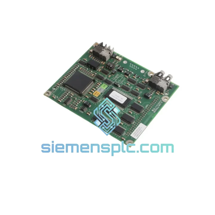
Request verified availability, condition, replacement risk review, packing options and courier lead time for DAPU100 3ASC25H204.
Click Request Quote and the part number is inserted into the inquiry form automatically.
Core fields for model confirmation and RFQ routing. Detailed product narrative remains below.
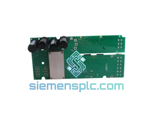
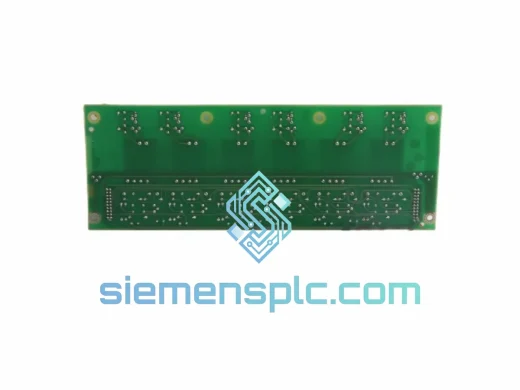
The DAPU100, referenced internally as 3ASC25H204, is a Drive Axis Pulse Unit board manufactured by ABB for integration within the Advant-series variable-speed drive control architecture. Its functional position sits at the boundary between the digital control domain and the power semiconductor switching domain: it receives firing commands from the axis controller via the backplane bus and translates them into precisely timed, galvanically isolated gate pulses delivered to IGBT or GTO power modules. This boundary role imposes strict requirements on timing determinism, isolation integrity, and fault propagation speed — all of which the DAPU100 addresses through dedicated hardware logic rather than firmware-mediated processing.
In multi-axis Advant drive cabinets, the DAPU100 operates as one of potentially several pulse units synchronized to a common PWM carrier reference. Each board governs a single three-phase bridge, generating six gate drive outputs — one per switch position — with hardware-enforced dead-time interlock between complementary devices in each phase leg. The board’s internal architecture ensures that no software fault, watchdog reset, or communication timeout can override the dead-time enforcement circuit, eliminating the shoot-through failure mode at the hardware level.
Applications span across high-performance AC motor drives, regenerative front-end converters, and active harmonic filter stages where switching precision directly affects output waveform quality, motor thermal loading, and filter component stress. The DAPU100 is not a general-purpose interface board; it is a purpose-engineered gate signal conditioner whose design parameters are matched to the electrical characteristics of ABB’s Advant power stack assemblies.
Real-time Stock & RFQ: [email protected] | WhatsApp: +86 18359268345
| Manufacturer | ABB Ltd. |
| Part Number | DAPU100 |
| Internal Reference | 3ASC25H204 |
| Module Function | Drive Axis Pulse Unit — PWM gate signal generation and distribution |
| Target Platform | ABB Advant Drive series (ACS, ACV, ACM, DCS families) |
| Form Factor | Eurocard PCB; backplane-mounted via DIN 41612 64-pin connector |
| Backplane Supply | +5 VDC logic rail; ±15 VDC analog rail (backplane-sourced, internally regulated) |
| Gate Drive Output Channels | 6 isolated outputs (3-phase full-bridge topology) |
| Channel Isolation Method | High-speed opto-electronic isolation per channel |
| Isolation Voltage (VIORM) | ≥ 560 V peak continuous; ≥ 4 kV surge (1.2/50 µs impulse) |
| Common-mode Transient Immunity | > 15 kV/µs (per IEC 60747-5-5) |
| PWM Carrier Frequency | 1.5 kHz – 12 kHz (drive firmware selectable) |
| Gate Pulse Propagation Delay | < 1.5 µs from backplane command receipt to output edge |
| Pulse Width Repeatability | ±50 ns cycle-to-cycle (hardware PWM ASIC, not firmware timer) |
| Dead-time Enforcement | Hardware combinational logic; minimum 2 µs; not software-overridable |
| Fault Output Response Time | < 10 µs from fault detection to backplane fault assertion |
| Backplane Bus Cycle Time | 1 ms (standard Advant configuration) |
| Operating Temperature | 0 °C to +55 °C (IEC 60068-2-1 / IEC 60068-2-2) |
| Storage Temperature | −25 °C to +70 °C |
| Relative Humidity | 5 % – 95 % RH, non-condensing (IEC 60068-2-78) |
| Vibration | IEC 60068-2-6: 10–150 Hz, 1 g sinusoidal |
| Mechanical Shock | IEC 60068-2-27: 15 g, 11 ms half-sine pulse |
| EMC Compliance | EN 61800-3 Category C2; EN 55011 Class A conducted/radiated |
| PCB Surface Protection | Acrylic conformal coating, IEC 60721-3-3 Class 3C2 |
| ESD Protection | TVS diode arrays on all backplane signal inputs |
| Board Power Dissipation | ≈ 1.8 W at full load (opto-drive stages + bus termination) |
| Weight | Approx. 80 g |
| Warranty | 12 months from dispatch date against manufacturing defects |
Dedicated PWM ASIC vs. Firmware Timer Architecture: The DAPU100 implements gate pulse generation through a purpose-built PWM ASIC rather than a general-purpose microcontroller timer peripheral. This distinction has measurable consequences: a firmware-driven timer is subject to interrupt service routine latency, which in a multi-tasking embedded environment can introduce cycle-to-cycle jitter of 200–800 ns depending on system load. The DAPU100’s ASIC generates switching edges with ±50 ns repeatability regardless of backplane communication activity or diagnostic polling cycles running concurrently on the axis controller. In high-frequency switching applications above 8 kHz, this jitter reduction directly translates to lower output current THD and reduced acoustic noise from the motor stator.
Opto-electronic Isolation and CMTI Rating: Each of the six gate drive channels passes through a dedicated high-speed optocoupler with a common-mode transient immunity (CMTI) exceeding 15 kV/µs. This specification addresses a specific failure mechanism in IGBT-based drives: during turn-off of a high-side switch, the collector-emitter voltage rises at rates of 5–10 kV/µs, inducing displacement currents through the parasitic capacitance of any isolation barrier in the gate drive path. If the isolation device’s CMTI is insufficient, these displacement currents generate spurious logic transitions that can falsely trigger the complementary low-side switch — a condition that results in a phase-leg short circuit within microseconds. The DAPU100’s 15 kV/µs CMTI rating provides a 1.5× to 3× margin over typical bus dV/dt values encountered in 690 V class drives.
Hardware Dead-time Interlock Circuit: The dead-time enforcement logic on the DAPU100 is implemented in combinational gate logic with no programmable element in the signal path. The minimum enforced interval of 2 µs is set by fixed RC timing networks on the PCB, not by a register value that firmware could inadvertently clear. This architecture means the interlock remains active during power-up sequencing, watchdog-triggered resets, and firmware update cycles — periods when software-based dead-time implementations are temporarily inactive and the power stage is most vulnerable to shoot-through. For 1200 V / 600 A IGBT modules with a typical tail current duration of 0.8–1.2 µs, the 2 µs minimum dead-time provides adequate margin across the full junction temperature range.
Backplane Bus Input Latching and Metastability Mitigation: The DAPU100’s backplane interface incorporates synchronous input latches clocked by the backplane reference clock, with a two-stage synchronizer on asynchronous inputs. This prevents metastability — a condition where a flip-flop input transitions near the clock edge, causing the output to settle to an indeterminate logic level for an extended period. In a gate drive application, a metastable event on a single PWM data bit would produce a pulse width error on one output channel for one switching cycle, manifesting as a current spike in the motor winding and a corresponding torque impulse. The synchronizer stages reduce the mean time between metastability events to values exceeding the expected service life of the drive system.
Thermal Distribution and PCB Layout Strategy: The board’s dominant heat sources — optocoupler LED drive transistors and bus termination resistors — are distributed across the PCB with deliberate spacing to prevent thermal coupling between adjacent channels. High-dissipation components are placed over copper pour areas that extend to the board’s edge connector frame, providing a conductive thermal path to the drive cabinet’s backplane structure. This passive thermal management approach eliminates the need for board-mounted heatsinks, which would increase insertion force on the backplane connector and complicate field replacement procedures.
Each DAPU100 3ASC25H204 unit leaving our Xiamen facility passes a structured pre-shipment inspection sequence. Under 10× optical magnification, solder joint geometry, component orientation, PCB trace condition, and connector pin alignment are verified against ABB reference documentation. Part number, date code, and revision marking on the board label are cross-checked against authenticated samples to confirm unit provenance and exclude counterfeit or remarked components.
Functional bench testing applies backplane supply voltages (+5 VDC, ±15 VDC) and monitors internal power rail regulation, fault output logic states, and optocoupler continuity across all six gate drive channels using calibrated instrumentation. Units passing all inspection stages are individually placed in anti-static shielding bags, cushioned in die-cut foam inserts, and sealed in double-wall cartons with tamper-evident tape. A signed inspection record accompanies each shipment; a certificate of conformance is available on request for procurement and quality management documentation.
Export logistics from Xiamen operate through DHL Express, FedEx International Priority, and UPS Worldwide Expedited. Typical transit times: 3–5 business days to Western Europe, 4–6 days to North America, 2–4 days to Southeast Asia and Australia. For volume orders, sea freight consolidation through Xiamen Port is available with full export documentation — commercial invoice, packing list, certificate of origin, and HS code classification support. All consignments are insured at declared value. Tracking references are issued at the time of dispatch and communicated by email.
Email: [email protected]
WhatsApp: +86 18359268345
Web: siemensplc.com
Location: Xiamen, China
© 2026 siemensplc.com. All rights reserved.
We check the full part number, brand, series and visible nameplate information before quotation.
Sales confirms stock path, condition option, quantity and realistic lead time for export dispatch.
DHL, FedEx, UPS or buyer courier arrangements can be reviewed with packing requirements.
Similar brand or category products for fast comparison and multi-item RFQ lists.