ABB
RFQ Ready
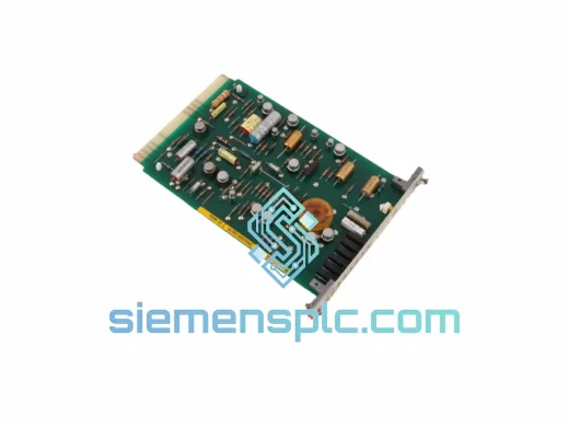
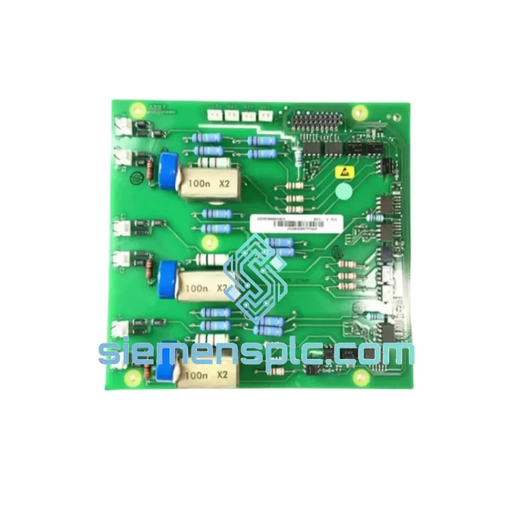
ABB YPK113A 61002774 Drive Control Board
In-Stock Xiamen
Origin SE
Drive Control Board
Request verified availability, condition, replacement risk review, packing options and courier lead time for 1SFB536068D1003.
Click Request Quote and the part number is inserted into the inquiry form automatically.
Core fields for model confirmation and RFQ routing. Detailed product narrative remains below.
The ABB 1SFB536068D1003 is the dedicated control printed circuit board (PCB) embedded within ABB’s AF Series contactor platform. Its function is not peripheral — it is the core switching intelligence that converts incoming control voltage into a precisely timed electromagnetic coil energization sequence, governs inrush current suppression during pull-in, and maintains the holding current at a fraction of the pick-up value through ABB’s Electronic Coil Technology (ECT). Without this board operating within specification, the contactor cannot execute reliable make-and-break operations, auxiliary contact signaling degrades, and the wide-range AC/DC coil compatibility that defines the AF Series is lost entirely.
AF Series contactors are deployed across motor control centers (MCCs), soft-starter bypass circuits, capacitor bank switching panels, and safety-rated motor starter assemblies in industries ranging from oil and gas to food processing. The 1SFB536068D1003 PCB is the component that makes the AF contactor’s coil voltage universality — typically 24–500 V AC/DC on a single board — physically possible. It achieves this through an onboard rectifier and voltage regulation stage that normalizes the incoming supply before driving the coil electromagnet, eliminating the need for separate AC and DC coil variants in the same panel design.
📧 Real-time Stock & RFQ: [email protected] | WhatsApp: +86 18359268345
| Parameter | Value / Description |
|---|---|
| Part Number | 1SFB536068D1003 |
| Manufacturer | ABB |
| Component Classification | Contactor Control PCB – Electronic Coil Drive Board |
| Compatible Platform | ABB AF Series Contactors (ECT – Electronic Coil Technology) |
| Coil Voltage Range (typical AF Series) | 24–500 V AC 50/60 Hz / 24–500 V DC (wide-range, single board) |
| Coil Power Consumption – Pick-up | High inrush (controlled by onboard ECT inrush limiter circuit) |
| Coil Power Consumption – Holding | Reduced holding current via PWM regulation stage on PCB |
| Auxiliary Contact Interface | Onboard signal conditioning for 1NO+1NC standard auxiliary outputs |
| Operating Temperature | -25 °C to +60 °C (storage: -40 °C to +70 °C) |
| Pollution Degree | 3 (per IEC 60947-1) |
| Degree of Protection | IP20 (within contactor housing) |
| Compliance | CE, IEC 60947-4-1, RoHS |
| PCB Form Factor | Plug-in module, direct replacement within AF contactor housing |
| Condition Available | New / Surplus New |
| Warranty | 12 months against manufacturing defects from dispatch date |
The 1SFB536068D1003 implements ABB’s Electronic Coil Technology through a multi-stage power conditioning and drive architecture on a single compact PCB. Understanding its hardware logic is essential for maintenance engineers diagnosing contactor faults at the board level.
Input Rectification and Voltage Normalization: The board accepts a wide AC/DC input range through a full-bridge rectifier stage. This rectified DC bus feeds a voltage regulation circuit that clamps the drive signal to a stable reference regardless of whether the incoming supply is 24 V DC from a PLC output card or 400 V AC from a panel bus. This single-board universality eliminates the coil variant proliferation that plagues older contactor designs.
Inrush Current Control (Pull-in Phase): During the pull-in phase, the electromagnet requires a high magnetomotive force to close the armature gap against the return spring. The PCB’s drive circuit delivers a controlled high-current pulse — typically 6–10× the holding current — for a defined window of approximately 50–100 ms. This is managed by a timed gate circuit that prevents sustained high-current drive, protecting both the coil winding and the PCB’s own drive transistors from thermal stress.
PWM Holding Current Regulation: Once the armature is seated, the PCB transitions to a pulse-width modulated (PWM) holding mode. The duty cycle is reduced to maintain just sufficient flux to hold the armature closed — typically 10–20% of the pick-up current. This dramatically reduces coil heating, extends insulation life, and lowers panel thermal load in high-density MCC installations.
EMC Design: The board incorporates transient voltage suppression (TVS) diodes across the input stage and snubber networks across the drive transistors to suppress switching transients. This is critical in environments with variable-frequency drives (VFDs), thyristor controllers, or large inductive loads sharing the same panel bus, where conducted EMI can reach levels that destroy unprotected control electronics.
Auxiliary Contact Signal Conditioning: The PCB interfaces with the contactor’s auxiliary contact bridge through a dedicated signal path that maintains contact state integrity independent of the main coil drive circuit. This ensures that PLC digital input cards and safety relay monitoring circuits receive clean, bounce-free status signals even during the mechanical transition period of the main contacts.
Every ABB 1SFB536068D1003 unit dispatched from our Xiamen, China facility is a genuine ABB OEM component. We maintain sourcing relationships with authorized ABB distributors and verified surplus channels, and every incoming batch undergoes a structured intake inspection: visual examination of PCB surface condition, solder joint integrity, component seating, and label authenticity against ABB’s known part marking standards. Units that do not pass intake inspection are quarantined and not offered for sale.
Packaging is ESD-safe anti-static bag with foam cushioning inside a rigid outer carton, sized to prevent board flex during transit. Each shipment includes a packing slip and inspection record. Sourcing documentation — including distributor invoices and lot traceability records — is available upon request for regulated procurement processes in aerospace, defense, and pharmaceutical manufacturing environments.
From Xiamen, we ship via DHL Express, FedEx International Priority, and UPS Worldwide Express. Typical transit times: Southeast Asia 2–3 days, Europe 3–5 days, North America 4–6 days, Middle East 3–5 days. For bulk orders, sea freight consolidation is available with full export documentation including commercial invoice, packing list, and certificate of origin. Emergency same-day dispatch is available for confirmed in-stock items ordered before 14:00 CST.
All units sold as new or surplus-new carry a 12-month warranty against manufacturing defects, covering failure under normal operating conditions within the specified electrical parameters. Warranty claims are processed within 5 business days of receipt of the returned unit.
📧 Email: [email protected]
💬 WhatsApp: +86 18359268345
🌐 Web: siemensplc.com
📍 Location: Xiamen, China
© 2026 siemensplc.com. All rights reserved.
We check the full part number, brand, series and visible nameplate information before quotation.
Sales confirms stock path, condition option, quantity and realistic lead time for export dispatch.
DHL, FedEx, UPS or buyer courier arrangements can be reviewed with packing requirements.
Similar brand or category products for fast comparison and multi-item RFQ lists.