ABB
In Stock OK
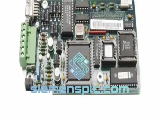
ABB 3BHB003230R0101 Power Board Assembly – ACS6000
Request verified availability, condition, replacement risk review, packing options and courier lead time for 3BHB003230R0101.
BrandABB
Part Number3BHB003230R0101
ConditionAvailability Check
Lead TimeRFQ Confirmation
DocumentsDatasheet / photos by RFQ
ShippingExport packing available
Auto-filled RFQ
3BHB003230R0101
Click Request Quote and the part number is inserted into the inquiry form automatically.
- Reply by email: [email protected]
- WhatsApp / Tel: +86 18359268345
- Mon-Sat 9:00-18:00 GMT+8
Procurement Data
Key Product Information
Core fields for model confirmation and RFQ routing. Detailed product narrative remains below.
- Brand
- ABB
- Primary Part Number
- 3BHB003230R0101
- Product Type
- Power Board Assembly
- Product Family
- Other series
- Manufacturer
- ABB Ltd. (ASEA Brown Boveri)
- Country of Origin
- SE
- Catalog Category
- Motor Drives
- Warranty
- 12 months from shipment date
Model confirmed for inquiry
3BHB003230R0101
Send quantity, destination and urgency. The RFQ form keeps this part number attached.
Request Quote
Product Overview
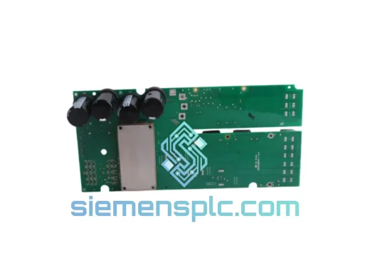
ABB 3BHB003230R0101: Gate Drive Interface Board for ACS6000 Medium-Voltage IGCT Drive Systems
The ABB 3BHB003230R0101 is a factory-original power board assembly purpose-built for the ACS6000 medium-voltage AC drive platform. The ACS6000 series spans a power range of 3 MW to 27 MW and is deployed in applications where process continuity is non-negotiable: LNG compressor trains, marine shaft drives, mine winding engines, and high-capacity water injection pumps. Within the ACS6000 cabinet, this board functions as the primary electrical interface between the drive’s DSP-based control processor and the IGCT (Integrated Gate-Commutated Thyristor) power switching stage. Its role is not peripheral — it is the component through which every gate command, every DC bus voltage sample, and every hardware protection signal must pass. Degradation or failure of this board does not produce a graceful performance reduction; it produces an immediate drive trip or, in worst-case scenarios, an uncontrolled IGCT commutation failure.
The ACS6000 uses Direct Torque Control (DTC), ABB’s proprietary motor control algorithm that computes torque and flux references every 25 microseconds without a shaft encoder. DTC’s performance advantage over conventional vector control depends entirely on the accuracy and latency of the feedback signals processed by the power board. DC bus voltage measurements must be sampled synchronously with the PWM carrier to avoid aliasing errors that would corrupt the flux estimator. Phase current transducer outputs must be conditioned to within ±0.5% linearity across the full operating temperature range. Gate pulse commands must be delivered to the IGCT gate units with sub-microsecond jitter — asymmetric gate timing across parallel thyristor stacks produces unequal current sharing, localized thermal stress, and accelerated device aging. The 3BHB003230R0101 is designed to meet all three requirements simultaneously, in a continuous-duty industrial environment, for the rated service life of the drive.
This board is not a generic PCB assembly that can be substituted with an equivalent-specification alternative. Its propagation delays, analog filter corner frequencies, and fault latch threshold voltages are calibrated to the ACS6000 system’s control timing model. Introducing a board with different electrical characteristics — even within nominal tolerance bands — can produce subtle control instabilities that manifest only under specific load transient conditions, making root-cause diagnosis extremely difficult. The only operationally safe replacement is the OEM part: ABB 3BHB003230R0101.
Real-time Stock & RFQ: [email protected] | WhatsApp: +86 18359268345
Technical Parameters
| Parameter | Specification |
|---|---|
| Part Number | 3BHB003230R0101 |
| Manufacturer | ABB Ltd. (ASEA Brown Boveri) |
| Assembly Classification | Gate Drive Interface / Power Board PCB Assembly |
| Compatible Drive Platform | ABB ACS6000 Medium-Voltage AC Drive |
| Drive Power Range | 3 MW – 27 MW |
| Drive Voltage Class | 3.0 kV – 6.9 kV (line-to-line, motor terminal) |
| Power Stage Topology | IGCT (Integrated Gate-Commutated Thyristor), 3-level NPC or equivalent |
| Control Algorithm | Direct Torque Control (DTC), 25 µs torque control cycle |
| Gate Signal Transmission | Fiber-optic isolated channels (galvanic isolation, kV-class) |
| DC Bus Voltage Feedback | Resistive divider network, synchronized ADC sampling |
| Current Feedback Interface | Analog inputs from phase current transducers (LEM or equivalent) |
| Hardware Fault Response Time | < 10 µs (hardware latch, independent of DSP loop) |
| PCB Construction | Multi-layer, conformal-coated, ESD-classified |
| Operating Ambient Temperature | 0 °C to +55 °C (inside drive cabinet) |
| Storage Temperature Range | -25 °C to +70 °C |
| Relative Humidity | 5% – 95% RH, non-condensing |
| Unit Weight | Approx. 1,220 g |
| Country of Origin | Germany |
| Warranty | 12 months from shipment date |
| Supply Condition | New OEM / Tested Surplus (inspected before dispatch) |
Hardware Logical Analysis
The 3BHB003230R0101 sits at the boundary between the low-voltage control domain and the high-energy switching domain — a position that imposes requirements on isolation architecture, signal conditioning bandwidth, and protection response time that are not found in standard industrial PCB designs.
Fiber-Optic Gate Isolation Architecture: Gate commands originating from the ACS6000 control processor are transmitted to the power board via fiber-optic links. This approach provides galvanic isolation rated to withstand the full common-mode voltage present between the control-voltage reference (24 VDC) and the IGCT anode potential, which can reach several kilovolts during normal commutation. Beyond isolation voltage, the fiber interface eliminates the coupling path for common-mode transients generated by IGCT turn-off events. IGCT commutation produces dV/dt rates exceeding 5 kV/µs on the DC bus; a copper-based gate signal path would inject these transients directly into the control signal, producing false gate triggers or corrupted feedback data. The fiber-optic architecture removes this failure mode entirely.
EMC Design and Multi-Layer Stack-Up: The board’s PCB stack-up places dedicated ground planes between each signal layer, creating a distributed capacitive shield that suppresses inter-layer crosstalk from high-frequency switching noise. Analog input traces — carrying millivolt-level signals from current transducers — are routed away from digital clock lines and are terminated with LC filter networks whose corner frequencies are set below the PWM carrier frequency. Ferrite bead arrays on power supply rails attenuate conducted emissions from the drive’s internal SMPS. The combined effect maintains ADC measurement linearity within ±0.5% across the 0 °C to 55 °C operating range, which is the accuracy floor required for reliable overcurrent and DC overvoltage protection thresholds.
Hardware-First Fault Latch Logic: The board incorporates dedicated hardware fault latch circuits that assert a gate-block signal independently of the main DSP control loop. Detection of a DC bus overvoltage condition or an IGCT desaturation event triggers the latch within microseconds — a response time that is physically impossible to achieve through software interrupt handling on any general-purpose processor. This hardware-first protection philosophy is a deliberate architectural choice for IGCT topologies: the absence of a gate-off signal for even 200–300 microseconds during a fault event can result in thyristor latch-up and irreversible device destruction. The hardware latch eliminates this exposure regardless of the control processor’s current execution state.
Thermal Derating and Component Selection: Gate driver output stages and analog signal conditioning ICs are the primary heat sources on the board. ABB’s component selection targets junction temperatures at least 25 °C below maximum ratings at the 55 °C ambient limit, providing a thermal margin that directly extends mean time between failures in continuous-duty applications. Conformal coating on the PCB surface prevents moisture absorption and dendritic growth on high-impedance analog nodes — a failure mode that is particularly relevant in coastal industrial environments with elevated humidity.
System Integration Benefits
- Zero-Modification Drop-In Replacement: The 3BHB003230R0101 is a direct form-fit-function replacement for the factory-installed board. Connector pinouts, mounting hole patterns, and PCB outline dimensions are identical to the original. No firmware parameter adjustments, no connector rewiring, and no mechanical rework are required. The drive can be returned to service immediately after board exchange and a standard ACS6000 commissioning check sequence.
- Matched Propagation Delay for DTC Integrity: The board’s fiber-optic receive and transmit latency is matched to the ACS6000 DTC algorithm’s 25 µs torque control cycle. A non-OEM board with different propagation characteristics would introduce phase error in the gate pulse sequence, degrading torque ripple performance and potentially triggering nuisance overcurrent trips under high dynamic load conditions.
- Synchronous DC Bus Voltage Sampling: Onboard voltage divider circuits deliver DC link voltage data to the control processor at a sampling rate synchronized to the PWM carrier frequency. This synchronization prevents aliasing artifacts in the flux estimator, enabling the DTC algorithm to apply accurate active voltage compensation during load transients without requiring external measurement instrumentation.
- Diagnostic Register Mapping: Hardware fault latch outputs are mapped to the ACS6000 diagnostic register set. Maintenance engineers can retrieve fault timestamps, fault type codes, and pre-fault operating parameters via the CDP control panel or DriveWindow PC software — enabling structured root-cause analysis without disassembling the power stage or requiring oscilloscope access to internal nodes.
- Hot-Standby Redundancy Support: In dual-drive or N+1 redundancy configurations, the board’s fault latch state is readable by the master controller, supporting automatic transfer to the standby drive within the configured switchover time window. This capability is essential in applications where process interruption carries significant financial or safety consequences.
- Sustained EMC Certification Compliance: The ACS6000 system’s CE and applicable regional certifications are based on the complete assembly as tested by ABB. Substituting the power board with a non-OEM equivalent may invalidate the drive’s EMC certification, creating regulatory compliance exposure in markets where CE marking is a legal requirement for continued operation.
- Elimination of Compatibility Qualification Risk: Using the OEM board removes the need for compatibility testing, parameter verification, or engineering change order sign-off that would be required when introducing a non-standard replacement. In regulated industries — offshore oil and gas, nuclear auxiliary systems, municipal water treatment — change management procedures can add weeks to any non-standard repair cycle.
- Predictable Long-Term Spare Parts Availability: The ACS6000 platform has an installed base spanning more than two decades in heavy industry. Stocking the 3BHB003230R0101 as a critical spare eliminates the risk of extended unplanned downtime caused by procurement lead times during an emergency failure event, particularly in remote or offshore installations where logistics timelines are extended.
Quality Assurance & Global Logistics
Every 3BHB003230R0101 unit dispatched from our Xiamen facility is sourced from ABB’s authorized distribution network or verified OEM overstock channels. Each unit passes a structured incoming inspection protocol before entering inventory stock:
- Physical Integrity Inspection: Full examination for PCB delamination, thermally stressed components, corroded connector contacts, fractured solder joints, and evidence of prior unauthorized repair or component substitution.
- Functional Verification: Where test fixtures are available, boards are powered and gate signal I/O channels are verified against ABB’s published functional acceptance criteria before stock entry.
- ESD-Controlled Handling and Export Packaging: All boards are handled exclusively at grounded ESD workstations. Finished units are sealed in anti-static shielding bags, cushioned with conductive foam, and packed in rigid double-wall export cartons. Humidity indicator cards are included for ocean freight consignments.
- 12-Month Warranty Coverage: All units carry a 12-month warranty from the date of shipment, covering manufacturing defects and functional failures under normal operating conditions. Warranty claims are acknowledged within 3 business days with a defined resolution path.
From Xiamen, China, express freight reaches major industrial regions on the following typical schedules: Europe 3–5 business days (DHL/FedEx Express), North America 3–5 business days, Southeast Asia 1–3 business days, Middle East 3–4 business days, Australia 3–5 business days. Full export documentation — commercial invoice, packing list, certificate of origin, and HS code declaration — is prepared in-house to ensure smooth customs clearance at destination. For time-critical situations, same-day dispatch is available for confirmed in-stock units when orders are placed before 14:00 CST.
Contact Information
Email: [email protected]
WhatsApp: +86 18359268345
Web: siemensplc.com
Location: Xiamen, China
© 2026 siemensplc.com. All rights reserved.
Ready to quote
[email protected]
Send This Part Number to Sales
RFQ workflow
Quality workflow ->
Confirmation Process
01Model confirmation
We check the full part number, brand, series and visible nameplate information before quotation.
02Availability reply
Sales confirms stock path, condition option, quantity and realistic lead time for export dispatch.
03Packing & courier
DHL, FedEx, UPS or buyer courier arrangements can be reviewed with packing requirements.
Continue sourcing
Browse full catalog ->
Related Automation Parts
Similar brand or category products for fast comparison and multi-item RFQ lists.
ABB
RFQ Ready
ABB ZINT-592 Fieldbus Interface Board – ZINT Series
ACS Drive
Origin SE
Interface Board
ABB
RFQ Ready
ABB YPK113A 61002774 Drive Control Board
In-Stock Xiamen
Origin SE
Drive Control Board