ABB
RFQ Ready
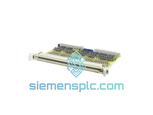
ABB YPM102A YT204001-AA Analog Output Module – AC 800M S800 I/O
S800
Origin SE
Analog Output Module
Request verified availability, condition, replacement risk review, packing options and courier lead time for 3BSE038415R1 AO810V2.
Click Request Quote and the part number is inserted into the inquiry form automatically.
Core fields for model confirmation and RFQ routing. Detailed product narrative remains below.
The 3BSE038415R1 is ABB’s second-generation 8-channel analog current output module, designated AO810V2, designed for deployment within S800 I/O stations connected to AC 800M distributed control system controllers. Its architectural role is unambiguous: it occupies the final deterministic conversion stage between a PM8xx processor’s resolved 16-bit output word and the physical 4–20 mA or 0–20 mA current signal delivered to field actuators — valve positioners, variable-frequency drive reference inputs, electro-pneumatic transducers, and process heater power controllers.
Current-mode transmission is the deliberate engineering basis for this output architecture. A current loop preserves signal accuracy independent of conductor resistance. Cable runs exceeding 300 m — routine in refinery pipe racks, offshore platform cable trays, and large-scale power generation switchgear rooms — introduce resistive losses that degrade voltage signals but impose no accuracy penalty on loop current, provided total loop impedance remains within the 750 Ω compliance ceiling. This property eliminates the class of calibration drift errors that voltage-output installations require periodic compensation to manage, reducing scheduled maintenance burden on instrument technicians across the asset lifecycle.
The V2 designation reflects three substantive hardware revisions relative to the original AO810 (3BSE008546R1). The DAC output stage temperature coefficient was tightened from ±100 ppm/°C to ±50 ppm/°C, halving thermal drift contribution across the 0–55 °C operating envelope. Per-channel open-circuit and overrange diagnostics were added, each surfaced as discrete status bits in the Modulebus status word rather than a single module-level fault flag — enabling fault isolation at the individual channel level without field inspection. Firmware compatibility was extended to AC 800M baseline v5.0 and later, permitting deployment in controller fleets upgraded to current software releases without a parallel hardware upgrade cycle. Mechanically, the AO810V2 is dimensionally identical to its predecessor and installs into any TB820V2 or TB840A terminal base without modification to field wiring, cable schedules, or cabinet layout drawings.
In a representative cascade control scheme — for example, a flow-pressure cascade on a gas compression train — the AO810V2 executes the output step of the outer pressure loop. The controller resolves the outer loop PID at its configured task period (typically 50–250 ms for pressure), writes the computed flow setpoint to the module’s output register, and the module drives the corresponding current to the flow control valve positioner within one additional Modulebus transfer cycle (~1 ms). The deterministic, bounded latency of this output path permits the inner flow loop to be tuned at bandwidths consistent with pneumatic actuator dynamics without introducing unpredictable output delays that would destabilize the cascade structure.
Real-time Stock & RFQ: [email protected] | WhatsApp: +86 18359268345
| Parameter | Specification |
|---|---|
| ABB Part Number | 3BSE038415R1 |
| Hardware Designation | AO810V2 |
| Manufacturer | ABB (Asea Brown Boveri) |
| Compatible Platform | AC 800M DCS / S800 I/O Station |
| Module Function | 8-Channel Analog Current Output |
| Output Signal Ranges | 4–20 mA or 0–20 mA, software-selectable per channel |
| DAC Resolution | 12-bit (4,096 discrete levels) |
| Current Step Size (4–20 mA range) | ≈ 3.91 µA per LSB |
| Output Accuracy | ±0.1% of full scale at 25 °C |
| Temperature Coefficient (V2) | ±50 ppm/°C |
| Maximum Loop Resistance | 750 Ω per channel |
| Compliance Voltage | ≥ 15 V at 20 mA into 750 Ω |
| Channel-to-Bus Isolation | 500 V AC, 1-minute withstand |
| Channel-to-Channel Isolation | Common return (not individually isolated) |
| Backplane Interface | S800 Modulebus (ABB proprietary) |
| Module Power Consumption | ≈ 2.5 W (bus-powered, no field load) |
| Operating Temperature Range | 0 °C to +55 °C |
| Storage Temperature Range | −40 °C to +70 °C |
| Relative Humidity | 5–95% RH, non-condensing |
| Enclosure Protection Rating | IP20 |
| Physical Dimensions (W×H×D) | 40 × 130 × 100 mm |
| Module Weight | ≈ 180 g |
| Hazardous Area Certification | ATEX Ex nA IIC T4 (Zone 2) |
| Additional Certifications | CE, UL |
| Compatible PM Controllers | PM851, PM856, PM860, PM861, PM864, PM866 |
| Minimum Firmware Baseline | AC 800M v5.0 |
| Compatible Terminal Bases | TB820V2, TB840A |
| Warranty | 12 months from shipment date |
The AO810V2 assigns one dedicated 12-bit DAC to each channel pair, sharing a precision bandgap voltage reference within the pair. Confining the reference to a two-channel group — rather than distributing a single reference across all eight channels — limits inter-channel reference noise coupling while keeping total power dissipation within the 2.5 W bus budget. This constraint is significant in densely populated I/O stations where thermal accumulation across adjacent modules is a cabinet thermal design consideration.
Each DAC output voltage feeds a high-side voltage-to-current converter implemented in a Howland current pump topology. This configuration actively regulates loop current against load resistance variation across the full 0–750 Ω compliance range. The controller does not need to apply cable-impedance compensation in software to maintain output accuracy at varying field device input impedances — the hardware absorbs that variability at the analog output stage, keeping the control application layer independent of field wiring characteristics.
EMC hardening addresses three distinct coupling paths. At the PCB level, analog output traces are routed on a dedicated inner copper layer with a continuous ground plane separating the analog and digital sections, attenuating capacitive coupling of Modulebus switching transients into the DAC output path. At the field terminal interface, ferrite bead filters on each channel terminal suppress conducted emissions in the 150 kHz–30 MHz band, consistent with IEC 61000-4-6 Level 3 immunity requirements for process control equipment in industrial environments. At the module housing level, the die-cast enclosure provides a Faraday shield that reduces radiated field coupling from adjacent relay output or switched-mode power supply modules sharing the same I/O station — a relevant consideration in compact cabinet designs where module-to-module spacing is 40 mm or less.
Open-circuit detection uses a low-level sense current injected into the loop when the commanded output falls below 1 mA. If measured loop impedance exceeds approximately 10 kΩ — the threshold corresponding to a broken conductor or disconnected field device terminal — the module asserts a channel-specific fault bit in the Modulebus status word within the current scan cycle. This fault propagates to the AC 800M controller and is logged in ABB System 800xA with a timestamp resolution matching the controller task period, enabling maintenance teams to correlate fault events with process historian data without manual time-alignment.
The Modulebus interface logic operates at 3.3 V CMOS levels and is galvanically isolated from the 24 V field output stage at 500 V AC. This isolation boundary eliminates ground loop paths between the DCS backplane reference and field wiring ground — a common source of DC offset errors in installations where field devices are grounded at multiple points along the cable run, a topology frequently encountered in older plant infrastructure where grounding practices were not uniformly enforced during original construction.
Every ABB 3BSE038415R1 AO810V2 unit dispatched from our Xiamen, China operations center is sourced through verified ABB-authorized distribution channels. Pre-shipment inspection covers three stages: physical examination of PCB, connector pins, locking tabs, and housing for transit or handling damage; a powered functional test confirming output current accuracy on all 8 channels against a calibrated reference load traceable to national measurement standards; and firmware version verification against the current ABB release matrix to confirm compatibility with the customer’s declared controller firmware baseline.
Packaging follows IEC 60068-2 transport conditioning guidelines. Each module is sealed in an anti-static polyethylene bag with desiccant packs and a humidity indicator card, then placed in a custom foam-lined corrugated carton rated for IATA Category II air freight handling. Export documentation — commercial invoice, packing list, certificate of conformity, and where required, a material safety data sheet — is prepared to satisfy customs clearance requirements in the European Union, North America, Southeast Asia, the Middle East, and Australia.
Primary international carriers are DHL Express, FedEx International Priority, and UPS Worldwide Express. Typical transit times are 3–5 business days to major industrial centers in Europe and North America, and 2–3 business days to destinations within Asia-Pacific. For plant shutdown and emergency maintenance scenarios, same-day dispatch is available for orders confirmed before 14:00 CST, subject to confirmed stock availability at time of order. A 12-month warranty from the shipment date covers all units against manufacturing defects and functional failure under normal operating conditions as defined in the ABB product specification. Warranty replacement units are dispatched on a cross-shipment basis for qualified accounts, minimizing plant downtime exposure during the return logistics cycle.
Email: [email protected]
WhatsApp: +86 18359268345
Web: siemensplc.com
Location: Xiamen, China
© 2026 siemensplc.com. All rights reserved.
We check the full part number, brand, series and visible nameplate information before quotation.
Sales confirms stock path, condition option, quantity and realistic lead time for export dispatch.
DHL, FedEx, UPS or buyer courier arrangements can be reviewed with packing requirements.
Similar brand or category products for fast comparison and multi-item RFQ lists.