ABB
In Stock OK
ABB P-HB-DOT-12010000 Safety Digital Output Module – AC500-S
Request verified availability, condition, replacement risk review, packing options and courier lead time for P-HB-DOT-12010000.
BrandABB
Part NumberP-HB-DOT-12010000
ConditionAvailability Check
Lead TimeRFQ Confirmation
DocumentsDatasheet / photos by RFQ
ShippingExport packing available
Auto-filled RFQ
P-HB-DOT-12010000
Click Request Quote and the part number is inserted into the inquiry form automatically.
- Reply by email: [email protected]
- WhatsApp / Tel: +86 18359268345
- Mon-Sat 9:00-18:00 GMT+8
Procurement Data
Key Product Information
Core fields for model confirmation and RFQ routing. Detailed product narrative remains below.
- Brand
- ABB
- Primary Part Number
- P-HB-DOT-12010000
- Product Type
- Safety Digital Output Module
- Series / Family
- AC500
- Manufacturer
- ABB
- Country of Origin
- SE
- Model Function
- Safety Digital Output (DO) — 12 channels
- Catalog Category
- I/O Modules
- Warranty
- 12 months from shipment date
Model confirmed for inquiry
P-HB-DOT-12010000
Send quantity, destination and urgency. The RFQ form keeps this part number attached.
Request Quote
Product Overview
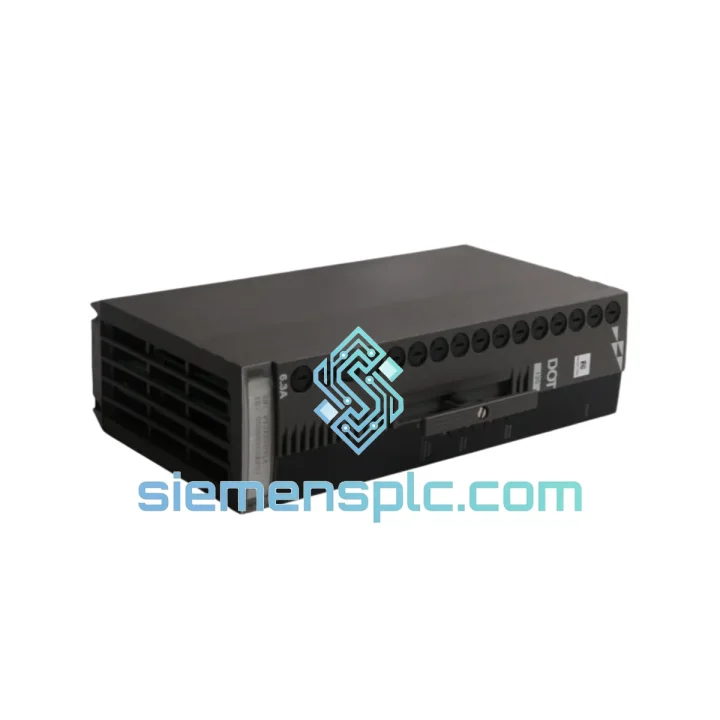
ABB P-HB-DOT-12010000: 12-Channel SIL 3 Safety Digital Output Module for AC500-S Functional Safety Controllers
The ABB P-HB-DOT-12010000 (catalog alias PHBDOT12010000) is a hardware-certified safety digital output module designed exclusively for integration within the ABB AC500-S functional safety PLC platform. It occupies the actuator-interface layer of a certified safety control loop — receiving validated output commands from the AC500-S CPU over the internal safety bus and translating them into 24 V DC transistor switching actions at the field level. The module carries IEC 61508 SIL 3 and EN ISO 13849-1 Performance Level e (PLe) certification, issued by TÜV Rheinland, covering both the hardware subsystem and its interaction with the AC500-S safety bus protocol.
In functional safety architectures, the output module is the final hardware element before the actuator. Its integrity directly determines whether a safety function — emergency stop, safe torque off, guard locking, or pressure relief — can be executed within the required reaction time and with the required diagnostic coverage. The P-HB-DOT-12010000 addresses this responsibility through a dual-channel transistor switching topology, hardware-level cross-channel comparison, and a deterministic bus interface that closes the diagnostic loop back to the CPU within a single bus cycle. No external safety relay, output monitor, or feedback wiring is required to achieve SIL 3 diagnostic coverage on any of its 12 output channels.
Real-time Stock & RFQ: [email protected] | WhatsApp: +86 18359268345
Technical Parameters
| Manufacturer | ABB |
| Part Number | P-HB-DOT-12010000 |
| Catalog Alias | PHBDOT12010000 |
| Module Function | Safety Digital Output (DO) — 12 channels |
| Target Platform | ABB AC500-S Safety PLC |
| Safety Certification | IEC 61508 SIL 3 / EN ISO 13849-1 PLe (TÜV Rheinland) |
| Output Channel Count | 12 independent safety-rated digital output channels |
| Output Switching Technology | Solid-state MOSFET transistor, sourcing (PNP) |
| Nominal Supply Voltage | 24 V DC |
| Supply Voltage Tolerance | 20.4 V DC – 28.8 V DC (−15% / +20%) |
| Rated Output Current per Channel | 0.5 A continuous |
| Short-Circuit Protection | Electronic, per channel, auto-resetting after fault clearance |
| Open-Load Detection | Passive test pulse during de-energized state; no actuator activation |
| Cross-Fault Detection | Hardware ASIC cross-comparison, <1 ms discrepancy window |
| Bus Interface | AC500-S internal safety bus, CRC-16 protected, time-slot multiplexed |
| Mounting | DIN rail, snap-on to AC500-S CPU or expansion rack |
| Protection Class | IP20 |
| Operating Temperature | −25 °C to +60 °C |
| Storage Temperature | −40 °C to +70 °C |
| Relative Humidity | 5% – 95%, non-condensing |
| EMC Immunity | EN 61000-6-2; EFT/Burst 2 kV (EN 61000-4-4); Surge 1 kV L-L (EN 61000-4-5) |
| EMC Emission | EN 61000-6-4 |
| Certifications | CE, cULus, TÜV Rheinland |
| Country of Origin | Germany |
| Packaged Weight | Approx. 1,400 g |
| Warranty | 12 months from shipment date |
Hardware Logical Analysis
The P-HB-DOT-12010000 implements a series dual-switch topology at the transistor output stage. Each of the 12 safety channels is controlled by two independent MOSFET switching elements connected in series between the 24 V DC supply rail and the output terminal. A dedicated hardware ASIC monitors the gate drive signals and drain-source voltage of both transistors on every bus cycle. If the measured states of the two series elements diverge — for example, one transistor fails short while the other remains in the commanded state — the ASIC detects the discrepancy within a 1 ms window and asserts a channel fault flag. The affected channel is de-energized by the non-faulted transistor, and the fault is reported to the AC500-S CPU in the next bus frame. This mechanism achieves the hardware fault tolerance (HFT = 1) required for SIL 3 classification under IEC 61508-2 Table 4 without any software intervention.
The internal safety bus interface uses a time-slot multiplexed frame structure with CRC-16 error detection on every command and response frame. Each output command frame carries a monotonically incrementing sequence counter. The module validates the CRC and sequence counter before executing any output state change. A frame with a failed CRC or an out-of-sequence counter is discarded, and the module transitions to a defined safe state — all outputs de-energized — rather than executing a potentially corrupted command. This behavior satisfies the communication safety requirements of IEC 61784-3 for black-channel safety communication, where the transport medium is not assumed to be inherently safe.
EMC hardening is implemented at three levels. At the supply input, a common-mode choke combined with an X/Y capacitor network attenuates conducted interference on the 24 V DC rail before it reaches the logic circuitry. At the bus interface, optical isolation separates the bus logic ground from the output driver ground, preventing high-frequency switching transients generated by inductive loads from coupling back into the communication layer. At the PCB level, the layout uses a dedicated ground plane under the output driver section, physically separated from the logic ground plane, with a single-point star connection between the two planes at the power entry point. This three-layer approach allows the module to meet EN 61000-4-4 Level 3 (2 kV EFT/Burst) and EN 61000-4-5 Level 2 (1 kV surge, line-to-line) without external suppression components — a practical advantage in cabinet environments where contactors, solenoid valves, and motor drives generate repetitive inductive switching transients on shared 24 V DC distribution rails.
The open-load detection circuit operates during the de-energized state of each channel. A low-amplitude test current (below the actuator pull-in threshold) is injected into the output terminal, and the resulting voltage is measured by the ASIC. A broken field wire or disconnected actuator terminal presents a high-impedance path; the ASIC detects the absence of the expected return current and flags an open-load fault within one diagnostic cycle. Because the test current is below the actuator activation threshold, this diagnostic method does not generate spurious actuator movements and does not require the safety function to be suspended during the test — a requirement for continuous SIL 3 operation without scheduled proof-test interruptions.
System Integration Benefits
- Bounded output latency: The AC500-S safety bus operates on a configurable fixed cycle time with a minimum of 1 ms. Output state changes commanded by the CPU are applied to the physical terminals within one bus cycle plus the transistor switching time (<100 µs), giving integrators a deterministic worst-case reaction time for safety function response calculations under IEC 62061 Clause 6.2.
- Elimination of external safety relays: The module’s SIL 3-rated transistor outputs can directly drive actuators rated up to 0.5 A per channel, replacing external safety relay modules in many standard machine safety architectures. This reduces the component count in the safety chain, eliminates relay contact wear as a failure mode, and removes the associated wiring and terminal block requirements.
- Native diagnostic process image mapping: Channel-level fault codes — short-circuit, open-load, cross-fault, supply undervoltage — are mapped directly into the AC500-S CPU’s safety process image. The safety application program can read these codes without additional diagnostic polling routines or function block overhead, reducing CPU cycle load and simplifying the safety program structure.
- Slot-addressed rack expansion: Additional P-HB-DOT-12010000 modules are added to the AC500-S expansion rack without modifying the CPU program structure. The safety bus assigns slot addresses during rack initialization, and the CPU’s I/O configuration is updated automatically. This supports phased machine builds where output channel count is expanded after initial commissioning.
- Pre-certified function block library compatibility: ABB Automation Builder includes TÜV-certified safety function blocks — SF_EmergencyStop, SF_SafelyLimitedSpeed, SF_TwoHandControl, SF_GuardMonitoring — that interface directly with this module’s output channels. Using pre-certified function blocks reduces the application-level safety validation scope, as the function block’s PFH contribution is already documented in ABB’s safety manual.
- Mixed safety and standard I/O in a single rack: The AC500-S rack architecture supports co-location of safety-rated and standard I/O modules in the same physical rack. A single rack can serve both the safety control function and the standard machine control function, reducing cabinet space, backplane wiring, and hardware procurement complexity.
- Extended ambient temperature range without derating: The −25 °C to +60 °C operating range covers outdoor enclosures, unheated machine rooms, and high-ambient foundry or press environments. No output current derating is required within this range, simplifying the thermal design of the control cabinet.
- Software-guided proof test execution: ABB Automation Builder provides a structured proof-test procedure that exercises each output channel through the safety bus and verifies the diagnostic response without physical wiring changes or external test equipment. The proof-test results are logged with a timestamp and firmware version reference, supporting the periodic proof-test documentation requirements of IEC 61508 Part 2 Clause 7.4.
- Firmware and hardware revision traceability: The module stores its firmware version and hardware revision code in a bus-readable register. This data is accessible from the CPU program and can be logged to the machine’s maintenance record system, supporting lifecycle documentation requirements under IEC 61508 Part 3 and facilitating spare-part compatibility verification during maintenance intervals.
- Reduced SIL verification calculation effort: Because the module is certified as a subsystem with published PFH (Probability of dangerous Failure per Hour) and PFD (Probability of Failure on Demand) values in ABB’s safety manual, integrators can reference these values directly in their SIL verification calculations. Independent hardware fault tree analysis of the output switching stage is not required, reducing the engineering effort for the safety case documentation.
Quality Assurance & Global Logistics
Each P-HB-DOT-12010000 unit supplied through siemensplc.com is sourced from verified ABB authorized distribution channels or documented industrial surplus with full traceability records. Pre-shipment inspection covers four checkpoints: visual examination of housing integrity and label legibility, firmware version verification against ABB’s published release matrix, functional power-on test confirming safety bus communication establishment and internal diagnostic self-test completion, and serial number cross-reference against ABB production records where traceability data is available. Original ABB packaging — including the anti-static inner bag, foam insert, and factory seal — is preserved throughout the inspection process to prevent electrostatic discharge damage and maintain transit protection.
All shipments originate from our warehouse in Xiamen, China. Standard export documentation is prepared for every order: commercial invoice, packing list, certificate of origin, and HS code declaration (HS 8537.10) to facilitate customs clearance at the destination port. Preferred express carriers are DHL Express (2–5 business days to most destinations), FedEx International Priority, and UPS Worldwide Expedited. For volume orders, sea freight consolidation via Xiamen Port is available in both FCL and LCL configurations. All shipments carry transit insurance covering loss and physical damage. The 12-month warranty covers manufacturing defects; warranty claims are acknowledged within 24 hours and processed within 5 business days of receipt of the returned unit at our Xiamen facility.
Contact Information
Email: [email protected]
WhatsApp: +86 18359268345
Web: siemensplc.com
Location: Xiamen, China
© 2026 siemensplc.com. All rights reserved.
Ready to quote
[email protected]
Send This Part Number to Sales
RFQ workflow
Quality workflow ->
Confirmation Process
01Model confirmation
We check the full part number, brand, series and visible nameplate information before quotation.
02Availability reply
Sales confirms stock path, condition option, quantity and realistic lead time for export dispatch.
03Packing & courier
DHL, FedEx, UPS or buyer courier arrangements can be reviewed with packing requirements.
Continue sourcing
Browse full catalog ->
Related Automation Parts
Similar brand or category products for fast comparison and multi-item RFQ lists.

ABB
RFQ Ready
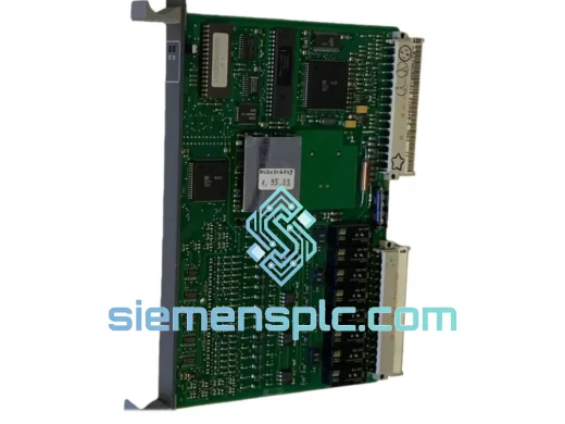
ABB GJR2389800R1210 PLC Temperature Input Module
AC500
Origin SE
PLC Temperature Input Module
ABB
RFQ Ready
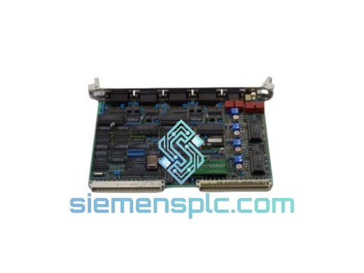
ABB GJR2390200R1211-83SR04G-E PLC Control Board – AC500 Series
AC500
Origin SE
PLC Control Board