Allen-Bradley
RFQ Ready
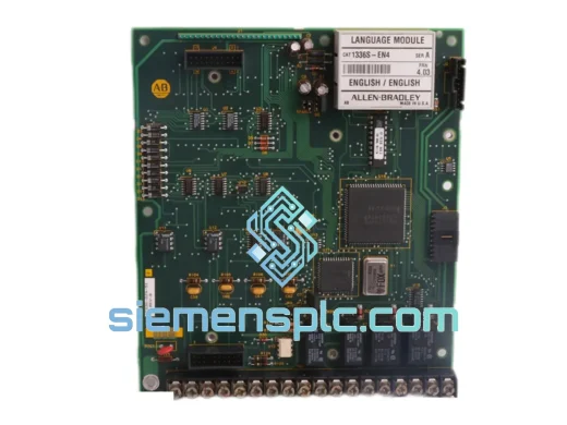
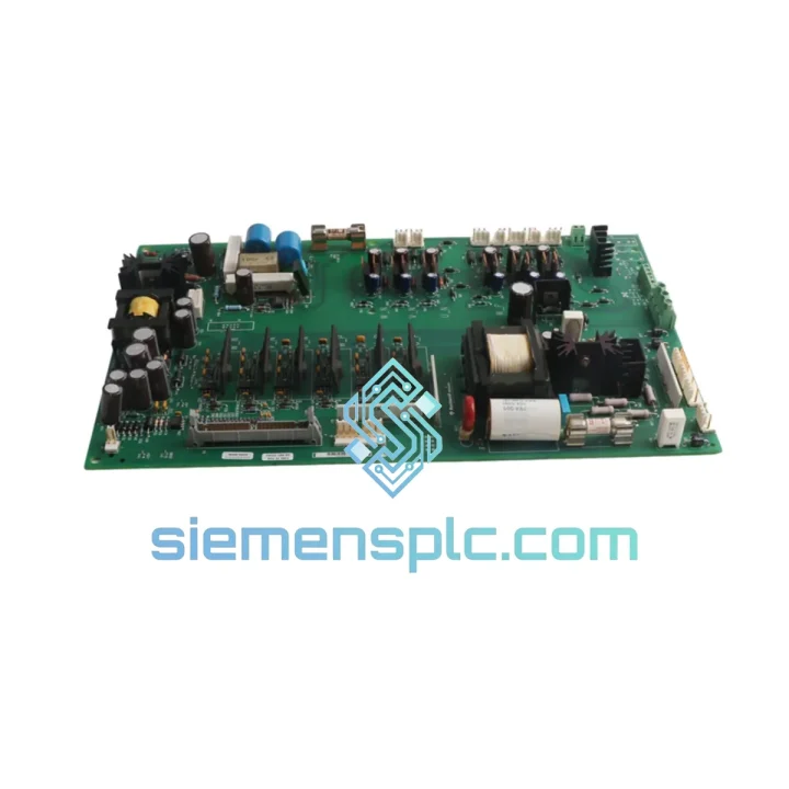
Allen-Bradley 1336T-MCB-SP34B 74101-772-54 AC Drive Control Board
Fast Replacement
Origin US
PLC Control Board
Request verified availability, condition, replacement risk review, packing options and courier lead time for 1336-BDB-SP30D.
Click Request Quote and the part number is inserted into the inquiry form automatically.
Core fields for model confirmation and RFQ routing. Detailed product narrative remains below.
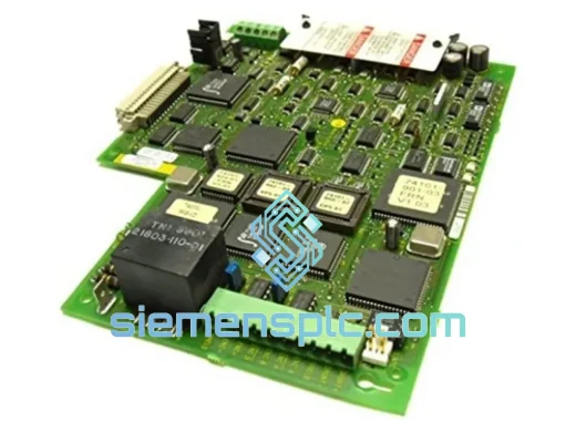
Your 1336 PLUS drive just tripped and won’t come back. The gate drive board is dead — you’ve confirmed it with a scope: no gate pulses on the IGBT legs, isolation fault on the opto-coupler rail, or a blown gate resistor. Every minute this line stays down is money walking out the door. The Allen-Bradley 1336-BDB-SP30D PCB Gate Drive Board is in stock at our Xiamen warehouse. We ship same day via DHL Express or FedEx International Priority. This is not a catalog listing — this is a live spare, tested, tagged, and ready to move.
URGENT REQUIREMENT? Contact: [email protected] | WhatsApp: +86 18359268345
| Parameter | Specification |
|---|---|
| Part Number | 1336-BDB-SP30D |
| Manufacturer | Allen-Bradley / Rockwell Automation |
| Board Function | IGBT Gate Drive & Isolation PCB |
| Compatible Drive Series | 1336 PLUS (1336F-xxxxx), 1336 PLUS II (1336S-xxxxx) |
| Power Rating Suffix | SP30D — 30 HP class gate drive |
| Gate Signal Method | Opto-coupler isolated PWM gate pulses |
| Bus Voltage Range | 380–480 VAC input (drive-dependent) |
| Isolation Voltage | Per Rockwell 1336 platform dielectric spec |
| Connector Interface | Direct plug-in to 1336 PLUS power stack — no wiring mod |
| Firmware Dependency | Compatible with all 1336 PLUS / PLUS II firmware revisions |
| Unit Weight | 1,260 g (board + anti-static packaging) |
| Origin | USA (Rockwell Automation OEM) |
| Stock Status | ✅ Ready to Ship — Xiamen Warehouse |
| Lead Time | Same-day dispatch on orders confirmed before 15:00 CST |
After ten years of field calls on 1336 PLUS drives, the gate drive board failure pattern is consistent. Here’s what you’ll see and what to do about it:
Fault Code F12 / F24 — Ground Fault or Transistor Fault: This is the most common symptom of a failing 1336-BDB-SP30D. The drive trips immediately on enable, or within seconds of running. Before condemning the gate drive board, verify the IGBT module itself isn’t shorted — measure collector-emitter resistance on all six legs with the drive de-energized and bus capacitors fully discharged (wait minimum 5 minutes after power-off, verify with a meter). If the IGBTs are intact and you’re still getting F12/F24, the gate drive board is the next suspect.
Opto-Coupler Degradation: The opto-couplers on the 1336-BDB-SP30D degrade over time in high-ambient-temperature environments. Symptoms include intermittent F12 faults that clear on reset but return under load, or asymmetric phase output (one phase leg switching late). A scope on the gate pins will show reduced or missing pulses on the affected leg. Replacement is the only fix — these components are not field-serviceable on the PCB.
Replacement Procedure — Step by Step:
Configuration Note — No DIP Switch or Address Setting Required: Unlike some drive boards that require manual address configuration, the 1336-BDB-SP30D is a passive gate drive board with no user-configurable switches. No parameter reset is required after replacement. However, if the drive was running a custom parameter set, verify that the drive parameters were not lost during the fault event — back up parameters via DriveExplorer or RSLogix 5000 before the replacement if possible.
The 1336-BDB-SP30D was designed for industrial environments where conditions are rarely ideal. The PCB substrate meets IPC Class 2 standards with conformal coating on production-run boards, providing resistance to condensation and airborne contaminants common in food processing, chemical, and coastal manufacturing facilities. The opto-couplers are rated for operation across a wide temperature range, maintaining signal integrity in ambient conditions up to 50°C — though sustained operation above 40°C will accelerate opto-coupler aging, which is why high-ambient installations should be prioritized for preventive replacement on a 5–7 year cycle.
Vibration resistance is inherent in the through-hole and press-fit connector design used on the 1336 platform — surface-mount components are minimized on the gate drive board specifically because Rockwell’s engineers understood that VFD enclosures in pump stations, compressor rooms, and mining applications see continuous mechanical vibration. The board’s mounting standoffs provide mechanical isolation from the power stack, reducing transmitted vibration to the PCB.
For installations in high-humidity environments — coastal facilities, paper mills, water treatment plants — inspect the board’s conformal coating condition during any planned maintenance window. Delamination or discoloration of the coating is an early indicator of moisture ingress and a leading predictor of opto-coupler failure. A board showing coating degradation should be scheduled for replacement before the next unplanned outage, not after.
All units supplied by us are stored in climate-controlled, anti-static environments. Boards are individually bagged in anti-static poly with desiccant, and inspected for conformal coating integrity, connector pin condition, and component seating before dispatch. We do not ship boards that show any evidence of prior installation damage, burn marks, or corrosion — if a unit doesn’t pass our bench check, it doesn’t ship.
Our warehouse is located in Xiamen, Fujian Province — one of China’s primary export hubs with direct access to DHL, FedEx, and UPS international gateways. This is not a drop-ship arrangement. Stock is physically on our shelves, and orders confirmed before 15:00 CST are dispatched the same business day.
Typical Transit Times from Xiamen:
Every shipment includes a commercial invoice with accurate HS code classification (HS 8537.10 for industrial control boards), declared value documentation, and a packing list. For customers in countries with import duty sensitivity, we can advise on documentation requirements — contact us before placing the order. We do not under-declare shipment values.
Tracking numbers are issued within 2 hours of dispatch and sent directly to your email. For critical shipments, we recommend DHL Express with the On-Demand Delivery option, which allows you to redirect the package to an alternate address or reschedule delivery if your site access changes during transit.
For orders requiring export documentation, CE declarations, or country-of-origin certificates, allow one additional business day for document preparation. Contact us at the time of order to initiate this process in parallel with picking and packing.
Email: [email protected]
WhatsApp: +86 18359268345
Web: siemensplc.com
© 2026 siemensplc.com. All rights reserved.
We check the full part number, brand, series and visible nameplate information before quotation.
Sales confirms stock path, condition option, quantity and realistic lead time for export dispatch.
DHL, FedEx, UPS or buyer courier arrangements can be reviewed with packing requirements.
Similar brand or category products for fast comparison and multi-item RFQ lists.