Allen-Bradley
RFQ Ready
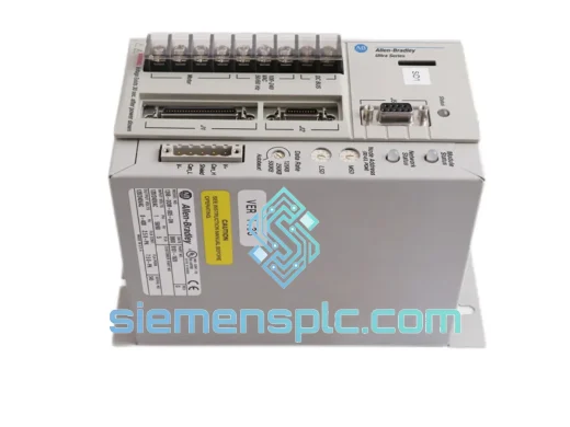
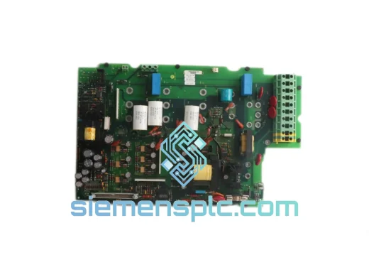
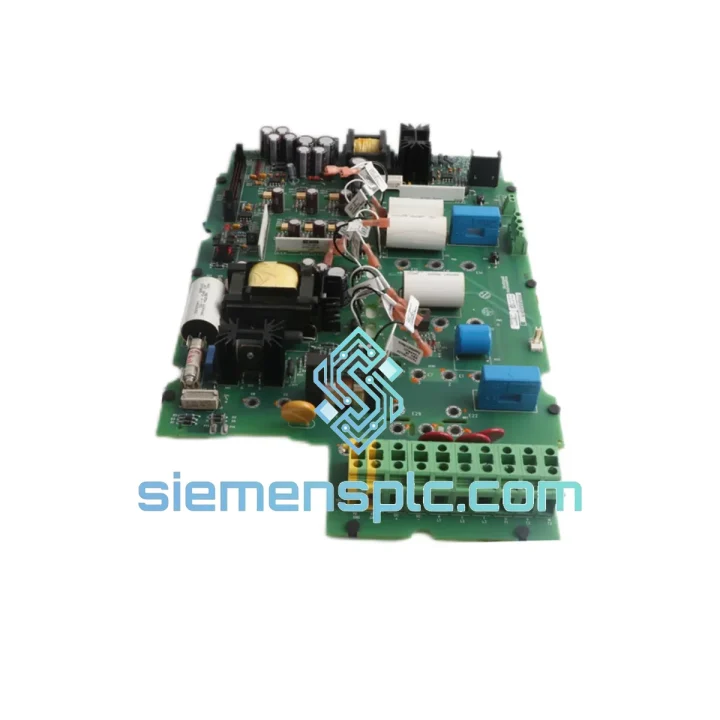
Allen-Bradley 1336-BDB-SP5C AC Drive Control Board
1336 PLUS Series
Origin US
AC Drive Spare Parts
Request verified availability, condition, replacement risk review, packing options and courier lead time for 1336-BDB-SP5D.
Click Request Quote and the part number is inserted into the inquiry form automatically.
Core fields for model confirmation and RFQ routing. Detailed product narrative remains below.
The 1336-BDB-SP5D is the primary control intelligence card for the Allen-Bradley 1336 PLUS family of AC variable-frequency drives (VFDs). Within the drive’s functional hierarchy, this board occupies the position between the operator interface and the power conversion stage — it receives speed and torque references, executes the V/Hz or closed-loop vector control algorithm, generates PWM gate signals for the IGBT bridge, and manages all diagnostic and fault-logging functions. Without a functional control board, the drive’s power section is inert regardless of its condition.
The 1336 PLUS platform was engineered for continuous-duty industrial environments: steel mills, water treatment stations, petrochemical compressor trains, and high-cycle packaging lines. The 1336-BDB-SP5D reflects that design intent — it is not a consumer-grade embedded controller but a purpose-built industrial compute node with deterministic scan-cycle behavior and hardware-level fault isolation.
Real-time Stock & RFQ: [email protected] | WhatsApp: +86 18359268345
| Part Number | 1336-BDB-SP5D |
| Manufacturer | Allen-Bradley / Rockwell Automation |
| Product Series | 1336 PLUS AC Variable-Frequency Drive |
| Component Classification | Main Drive Control PC Board |
| Control Architecture | V/Hz open-loop and sensorless vector (drive-dependent firmware) |
| PWM Output | Three-phase IGBT gate signal generation via isolated gate driver interface |
| Analog I/O | Multiple 0–10 V / 4–20 mA reference and feedback channels (drive-model dependent) |
| Digital I/O | Programmable discrete inputs/outputs for run, fault, direction, and speed preset commands |
| Communication Interface | Compatible with 1336-GM1/GM2 gate driver board; supports optional DPI/SCANport adapter modules |
| Fault Memory | Non-volatile fault queue retaining last fault codes across power cycles |
| Operating Temperature | 0 °C to +50 °C ambient (drive enclosure rated) |
| Storage Temperature | −40 °C to +85 °C |
| Humidity | 5–95% RH, non-condensing |
| Vibration Resistance | Per IEC 60068-2-6 (sinusoidal), IEC 60068-2-64 (random) |
| EMC Compliance | IEC 61800-3 Category C2 (drive-level); board-level shielding per OEM design |
| Weight | Approx. 1,540 g |
| Condition | Genuine OEM — Surplus / New Old Stock (NOS) |
| Warranty | 12 months functional warranty from date of shipment |
The 1336-BDB-SP5D’s hardware design reflects the engineering constraints of high-power industrial drive control, where a single board must simultaneously handle low-level analog signal conditioning, real-time PWM generation, and high-noise-immunity digital I/O — all within a chassis that sits adjacent to a multi-kilowatt power conversion stage.
Optical Isolation Architecture: All gate drive command signals leaving the control board toward the IGBT bridge pass through optocoupler barriers. This galvanic isolation prevents DC bus transients — which can reach several hundred volts in microseconds during switching events — from propagating back into the control logic. The isolation boundary is maintained at both the gate signal outputs and the DC bus voltage feedback inputs, ensuring the microcontroller’s reference ground remains stable regardless of switching noise on the power ground plane.
Analog Front-End Signal Conditioning: Speed reference inputs (0–10 V or 4–20 mA) pass through active low-pass filter stages before reaching the A/D converter. This filtering suppresses high-frequency noise injected by nearby contactors, relay coils, and cable capacitance — a common source of erratic speed behavior in poorly shielded panel installations. The filter corner frequency is set to reject noise above the control loop bandwidth without introducing phase lag that would destabilize the speed regulator.
PWM Generation and Dead-Time Insertion: The board’s PWM generation logic includes hardware-enforced dead-time insertion between complementary gate signals. This prevents shoot-through — the condition where both the upper and lower IGBTs in a phase leg conduct simultaneously, creating a direct short across the DC bus. Dead-time values are fixed in hardware, not software, ensuring they cannot be inadvertently overwritten by a firmware fault or parameter corruption event.
Non-Volatile Fault Logging: Fault codes are written to non-volatile memory on the board, not to volatile RAM. This means the fault queue survives a complete power loss, allowing maintenance engineers to read the fault history after an unplanned shutdown without requiring the drive to have remained powered. The fault log includes fault code, drive operating state at fault time, and output frequency — sufficient data to distinguish nuisance trips from genuine hardware faults.
EMC Design Practices: The board uses a multi-layer PCB with dedicated ground planes to minimize impedance in the return current paths. High-frequency bypass capacitors are placed at each IC power pin to suppress supply rail noise generated by the switching logic. Signal traces carrying analog references are routed away from digital clock lines and PWM outputs, reducing capacitive crosstalk that would otherwise appear as noise on the speed reference signal.
Every 1336-BDB-SP5D unit offered through siemensplc.com is sourced from decommissioned OEM equipment, authorized surplus channels, or verified new old stock — not from untracked grey-market brokers. Before dispatch, each board undergoes a structured inspection sequence:
Logistics operations are based in Xiamen, China, with daily dispatch via DHL Express, FedEx International Priority, and UPS Worldwide Expedited. Full tracking is provided at shipment. Typical transit times: 2–4 business days to Europe and North America, 1–3 business days to Southeast Asia. Customs documentation — commercial invoice, packing list, and HS code declaration — is prepared to minimize clearance delays at destination ports.
Email: [email protected]
WhatsApp: +86 18359268345
Web: siemensplc.com
Location: Xiamen, China
© 2026 siemensplc.com. All rights reserved.
We check the full part number, brand, series and visible nameplate information before quotation.
Sales confirms stock path, condition option, quantity and realistic lead time for export dispatch.
DHL, FedEx, UPS or buyer courier arrangements can be reviewed with packing requirements.
Similar brand or category products for fast comparison and multi-item RFQ lists.