Allen-Bradley
RFQ Ready
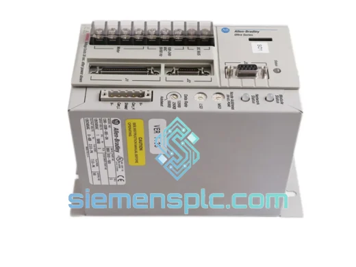
Allen-Bradley 1398-DDM-005-DN Servo Drive – 1398 ULTRA Series
5A AC/DC Axis Controller
Origin US
Servo Drive
Request verified availability, condition, replacement risk review, packing options and courier lead time for 135232-04.
Click Request Quote and the part number is inserted into the inquiry form automatically.
Core fields for model confirmation and RFQ routing. Detailed product narrative remains below.
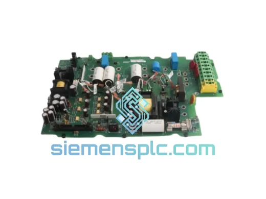
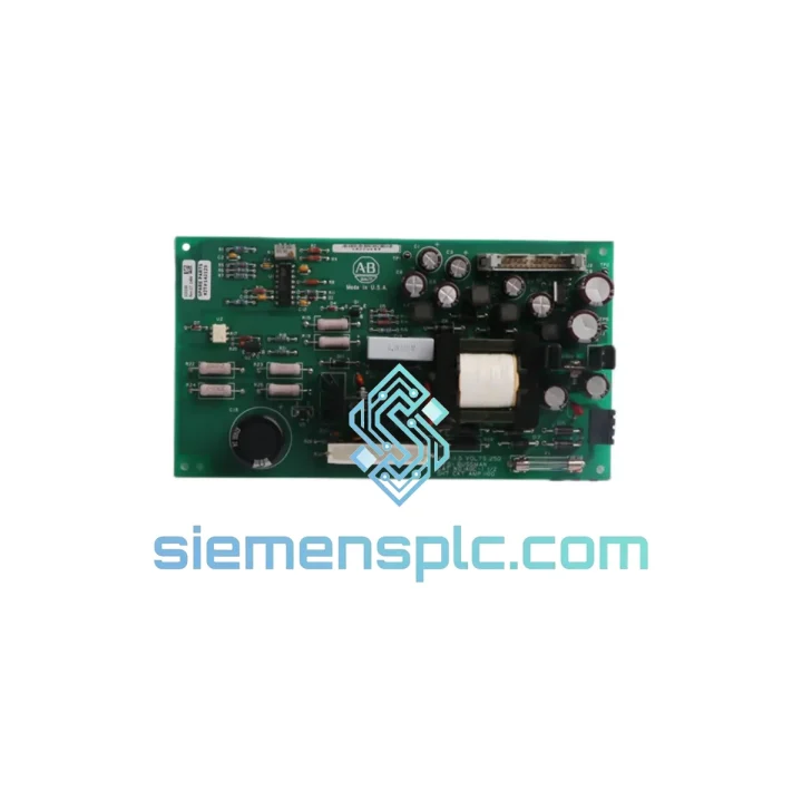
The Allen-Bradley 135232-04 (cross-reference: 142129, board revision 135230REV09) is the internal power supply board designed for the 1336 PLUS and 1336 PLUS II series AC variable frequency drives manufactured by Rockwell Automation. Within the drive’s power conversion chain, this board occupies the position between the rectified DC bus and the gate driver circuitry, generating the isolated auxiliary supply rails that power the IGBT gate drive stages, the control processor board, and the onboard diagnostic logic. Its correct operation is a prerequisite for any switching activity in the inverter section; a degraded or failed unit will suppress all PWM output and trigger a hardware fault latch that cannot be cleared by software alone.
The 1336 series was engineered for demanding industrial motor control applications — conveyors, compressors, pumps, and multi-axis coordinated drive systems — where supply rail stability directly determines torque linearity and speed regulation accuracy. The 135232-04 board provides the regulated voltages that sustain these performance characteristics across the full operating load range of the drive.
Real-time Stock & RFQ: [email protected] | WhatsApp: +86 18359268345
| Manufacturer | Allen-Bradley / Rockwell Automation |
| Primary Part Number | 135232-04 |
| Cross-Reference Numbers | 142129 / 135230REV09 |
| Board Revision | REV09 (latest validated revision for 1336 PLUS / PLUS II compatibility) |
| Component Classification | Internal Auxiliary Power Supply Board |
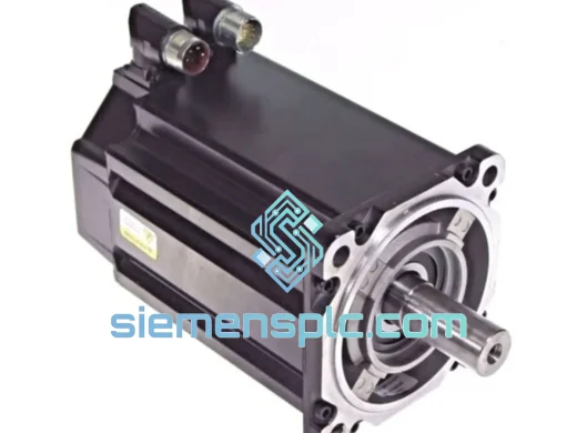
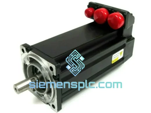
| Compatible Drive Series | Allen-Bradley 1336 PLUS, 1336 PLUS II AC Variable Frequency Drives |
| Primary Function | Isolated auxiliary DC rail generation for gate drivers, control board, and diagnostic logic |
| Input Source | Derived from internal DC bus (rectified mains, drive-dependent voltage) |
| Output Rails | Multiple isolated DC rails (±15 V gate drive bias, +5 V logic, +24 V auxiliary — per OEM schematic) |
| Isolation Architecture | Transformer-coupled flyback topology with per-channel optocoupler feedback |
| PCB Construction | Multi-layer FR4, conformal coat applied to exposed copper areas |
| Connector Interface | Board-to-board and wire-harness connectors per 1336 drive mechanical standard |
| Operating Temperature | 0 °C to +55 °C (ambient, within drive enclosure) |
| Country of Origin | USA |
| Condition Available | New / Surplus New (specify at RFQ) |
| Warranty | 12 months from date of shipment |
The 135232-04 board implements a multi-output flyback converter topology, which is the standard architecture for generating multiple galvanically isolated supply rails from a single high-voltage DC input in variable frequency drive applications. The primary winding is driven by a PWM controller IC operating at a fixed switching frequency — typically in the 50–100 kHz range for this class of board — which keeps transformer core size compact while maintaining adequate energy transfer at light load conditions.
Each secondary winding feeds a dedicated rectifier and LC filter stage, producing a regulated rail with isolation barriers rated to withstand the common-mode voltage transients that occur during IGBT switching events. The ±15 V gate drive rails are the most critical outputs: the +15 V forward bias must remain within ±0.5 V to ensure full IGBT saturation and minimum conduction loss, while the −15 V reverse bias must be stable to guarantee hard turn-off and prevent parasitic re-triggering of the gate during the dead-time interval. Any rail sag on these outputs directly translates to increased switching losses and elevated junction temperature in the IGBT modules.
The board’s feedback network uses optocoupler-based isolation to close the regulation loop across the isolation barrier. This design choice eliminates any direct electrical path between the high-voltage primary side and the low-voltage secondary control circuitry, which is essential for both operator safety and EMC compliance. The optocoupler’s CTR (current transfer ratio) aging characteristic is a known long-term failure mode in this class of board; REV09 incorporates component selection criteria that account for CTR degradation over a 10-year service life at rated operating temperature.
The conformal coating applied to the PCB surface provides protection against condensation and airborne conductive particulates — a relevant consideration in manufacturing environments where coolant mist, metallic dust, or chemical vapors are present. The coating does not impede thermal dissipation from the board’s power components, which are positioned to allow convective airflow from the drive’s internal fan system.
From an EMC standpoint, the switching frequency and transformer design are selected to place the fundamental and dominant harmonics outside the frequency bands most sensitive to conducted emissions limits under IEC 61800-3 (adjustable speed electrical power drive systems). The board’s layout routes high-di/dt switching loops in tight, low-inductance geometries to minimize radiated field generation at the source.
Every Allen-Bradley 135232-04 / 142129 / 135230REV09 board supplied by siemensplc.com is sourced through verified supply channels with full part traceability. Units are inspected against OEM physical and dimensional standards, including PCB markings, component date codes, solder joint condition, and connector integrity. Functional verification — including power-on rail measurement against OEM voltage specifications — is performed where test fixtures permit.
Shipments originate from Xiamen, China, with export documentation prepared as standard: commercial invoice, packing list, certificate of origin, and HS code classification. Carrier options include DHL Express, FedEx International Priority, and UPS Worldwide Expedited, with typical transit times of 3–7 business days to major industrial markets in Southeast Asia, the Middle East, Europe, and North America. Bulk orders are accommodated via sea freight with full container load (FCL) or less-than-container load (LCL) arrangements. All units are shipped in anti-static packaging with adequate mechanical protection for international transit. A 12-month warranty is issued with every shipment, covering functional failure under normal operating conditions.
Email: [email protected]
WhatsApp: +86 18359268345
Web: siemensplc.com
Location: Xiamen, China
© 2026 siemensplc.com. All rights reserved.
We check the full part number, brand, series and visible nameplate information before quotation.
Sales confirms stock path, condition option, quantity and realistic lead time for export dispatch.
DHL, FedEx, UPS or buyer courier arrangements can be reviewed with packing requirements.
Similar brand or category products for fast comparison and multi-item RFQ lists.