Allen-Bradley
In Stock OK
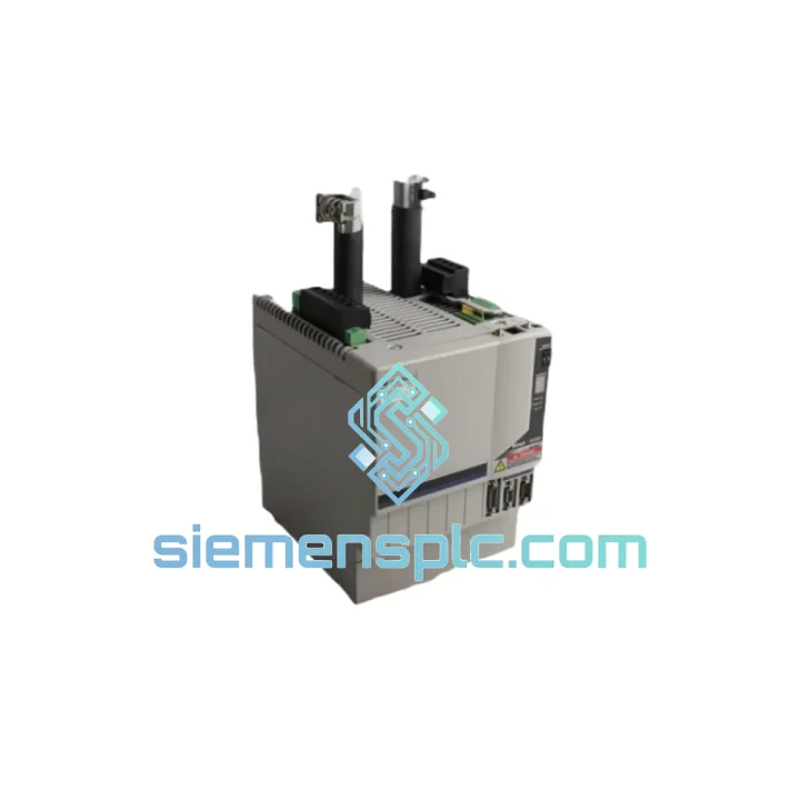
Allen-Bradley 2094-BC07-M05-S SER C Servo Drive Module – Kinetix 6000
Request verified availability, condition, replacement risk review, packing options and courier lead time for 2094-BC07-M05-S.
BrandAllen-Bradley
Part Number2094-BC07-M05-S
ConditionAvailability Check
Lead TimeRFQ Confirmation
DocumentsDatasheet / photos by RFQ
ShippingExport packing available
Auto-filled RFQ
2094-BC07-M05-S
Click Request Quote and the part number is inserted into the inquiry form automatically.
- Reply by email: [email protected]
- WhatsApp / Tel: +86 18359268345
- Mon-Sat 9:00-18:00 GMT+8
Procurement Data
Key Product Information
Core fields for model confirmation and RFQ routing. Detailed product narrative remains below.
- Brand
- Allen-Bradley
- Primary Part Number
- 2094-BC07-M05-S
- Product Type
- Servo Drive Module
- Series / Family
- Kinetix
- Manufacturer
- Allen-Bradley / Rockwell Automation
- Country of Origin
- US
- Catalog Category
- Motor Drives
- Operating Temp.
- 0 °C to +50 °C (derating above 40 °C)
- Warranty
- 12 months from date of shipment
Model confirmed for inquiry
2094-BC07-M05-S
Send quantity, destination and urgency. The RFQ form keeps this part number attached.
Request Quote
Product Overview
Allen-Bradley 2094-BC07-M05-S SER C — Kinetix 6000 Integrated Axis Module for Multi-Axis Servo Control
The 2094-BC07-M05-S SER C is the Integrated Axis Module (IAM) at the architectural center of a Kinetix 6000 multi-axis servo drive system. It performs two distinct power-conversion functions within a single chassis slot: AC-to-DC rectification via its 7 A RMS converter stage, and DC-to-AC inversion for the first servo axis via its 5 A RMS inverter stage. This dual-function architecture eliminates the standalone converter module required in earlier Kinetix generations, reducing panel real estate and inter-module wiring by a measurable margin.
The module communicates over a SERCOS II fiber-optic ring — an IEC 61491-compliant serial real-time protocol — at selectable cycle times of 2 ms or 4 ms. At 2 ms, the ring delivers position, velocity, and torque command data to all axes with deterministic jitter below 1 µs, a prerequisite for tight electronic gearing and cam-profile interpolation across multiple coordinated axes. The fiber medium provides inherent galvanic isolation between nodes and immunity to conducted EMI from adjacent power electronics.
Series C (SER C) represents the third hardware revision of this catalog number. Compared to SER A and SER B, SER C incorporates revised gate-drive circuitry for the IGBT inverter stage, updated thermal interface materials between the power module and heatsink, and firmware-level enhancements that expand compatibility with Studio 5000 Logix Designer v21 and later. The physical form factor and power-rail connector pinout remain backward-compatible with existing Kinetix 6000 power rail assemblies.
The integrated Safe Torque-Off (STO) function disables the IGBT gate signals via a dual-channel hardware path independent of the control processor. This architecture satisfies IEC 62061 SIL 2 and ISO 13849-1 PLd requirements for safety-rated axis disable without an external safety relay in the drive circuit, simplifying the safety architecture and reducing component count in CE-marked machinery.
Shared DC bus operation is a defining characteristic of the Kinetix 6000 platform. The IAM’s converter charges a common DC bus distributed across all Axis Expansion Modules (AMs) on the same power rail. Regenerative energy from decelerating axes flows back onto this bus and is immediately available to accelerating axes, reducing net energy drawn from the AC supply. In applications with balanced acceleration/deceleration profiles — packaging lines, palletizers, and printing presses — this energy exchange can reduce peak demand current by 20–35% compared to individual-drive architectures.
Feedback compatibility spans Stegmann Hi-resolution (multi-turn absolute, 262,144 counts/rev), incremental encoder (differential TTL), and resolver interfaces. The Hi-resolution feedback path supports absolute position retention across power cycles without a battery, eliminating homing routines after unplanned shutdowns — a significant operational advantage in continuous-process industries.
Real-time Stock & RFQ: [email protected] | WhatsApp: +86 18359268345
Technical Parameters
| Part Number | 2094-BC07-M05-S |
| Series Revision | SER C |
| Product Family | Kinetix 6000 Multi-Axis Servo Drive |
| Module Classification | Integrated Axis Module (IAM) |
| Manufacturer | Allen-Bradley / Rockwell Automation |
| Converter Output Current | 7 A RMS continuous |
| Inverter Output Current | 5 A RMS continuous / 10 A RMS peak (2 s) |
| AC Input Voltage | 195–264 V AC, 3-phase, 47–63 Hz |
| DC Bus Voltage | 375 V DC nominal (bus-sharing architecture) |
| Communication Protocol | SERCOS II fiber-optic ring (IEC 61491) |
| SERCOS Cycle Time | 2 ms / 4 ms selectable |
| Feedback Interfaces | Stegmann Hi-resolution absolute, incremental encoder (TTL), resolver |
| Safe Torque-Off (STO) | Dual-channel hardware, SIL 2 / PLd rated |
| Enclosure Rating | IP20 (panel-mount, open-type) |
| Operating Temperature | 0 °C to +50 °C (derating above 40 °C) |
| Storage Temperature | −40 °C to +85 °C |
| Relative Humidity | 5–95% non-condensing |
| Module Weight | Approx. 200 g (module only, excluding power rail) |
| Certifications | UL 508C, CE (LVD 2014/35/EU, EMC 2014/30/EU), cUL, RoHS |
| Functional Safety Standards | IEC 62061 SIL 2, ISO 13849-1 PLd |
| Warranty | 12 months from date of shipment |
Hardware Logical Analysis
The 2094-BC07-M05-S SER C is built around a three-stage power conversion topology. The input rectifier bridge converts 3-phase AC to an unregulated DC bus. An active pre-charge circuit limits inrush current during bus energization, protecting both the module’s capacitor bank and upstream fusing. The IGBT inverter stage uses a three-phase bridge configuration with gate-drive isolation between the control logic domain (3.3 V / 5 V CMOS) and the power domain (375 V DC bus), implemented via optocoupler-based gate drivers with under-voltage lockout (UVLO) protection on each gate channel.
EMC design follows a layered approach. The power stage PCB uses a four-layer stackup with dedicated ground planes to minimize loop inductance in the gate-drive return paths. DC bus conductors are routed as closely coupled pairs to reduce differential-mode emissions. The SERCOS II fiber interface provides complete galvanic isolation at the communication boundary, eliminating ground-loop coupling between the controller backplane and the drive chassis — a common EMI ingress path in copper-based fieldbus architectures.
The STO function is implemented as a dual-channel hardware interlock. Two independent input channels (STO-1 and STO-2) must both be de-energized to disable the gate-drive enable signals. The logic is implemented in discrete hardware — not in the main DSP firmware — ensuring that a firmware fault cannot inadvertently re-enable the gate drives while STO is asserted. This architecture satisfies the diagnostic coverage requirements for SIL 2 / PLd without requiring a separate safety-rated relay in the drive output circuit.
The Hi-resolution feedback interface uses a proprietary Stegmann protocol over a shielded differential pair. The encoder ASIC on the module decodes absolute position data at 262,144 counts per revolution with multi-turn capability up to 4,096 turns, providing a total position resolution of approximately 1.07 billion counts per mechanical revolution of the motor shaft. This resolution is sufficient for direct-drive torque motor applications where gearbox backlash cannot be tolerated.
System Integration Benefits
- Unified Studio 5000 Programming Environment — Motion axis configuration, PID tuning parameters, and safety function assignment are all managed within a single Studio 5000 Logix Designer project, eliminating the need for a separate drive commissioning tool and reducing configuration version-control complexity.
- Deterministic Real-Time Response — SERCOS II ring topology guarantees command delivery jitter below 1 µs at 2 ms cycle time, enabling electronic gearing ratios and cam profiles that require sub-millisecond axis synchronization across up to 16 axes on a single ring.
- Shared DC Bus Energy Recovery — Regenerative braking energy from decelerating axes is redistributed to accelerating axes on the same power rail without returning to the AC supply, reducing peak demand current and eliminating individual braking resistors in balanced-load applications.
- Integrated Safety Without External Relays — The hardware STO function eliminates the external safety relay and associated wiring in the drive output circuit for SIL 2 / PLd applications, reducing panel component count and simplifying IEC 62061 safety validation documentation.
- Absolute Position Retention Across Power Cycles — Stegmann Hi-resolution feedback retains absolute multi-turn position without a battery, eliminating homing sequences after unplanned shutdowns and reducing restart time in continuous-process applications.
- Scalable Axis Count on a Single Power Rail — One IAM supports up to seven additional Axis Expansion Modules on an 8-slot Kinetix 6000 power rail, allowing incremental axis addition as machine requirements grow without replacing the converter infrastructure.
- Transparent Drive Diagnostics via Logix — Drive fault codes, bus voltage, output current, and thermal status are accessible as standard Logix tags, enabling HMI display and historian logging without additional fieldbus gateways or proprietary diagnostic software.
- Fiber-Optic EMI Immunity — SERCOS II fiber eliminates conducted EMI coupling between the controller and drive, a critical advantage in environments with large VFDs, welding equipment, or high-frequency induction heating systems operating in proximity to the control cabinet.
- Backward Compatibility with Existing Power Rail Infrastructure — SER C maintains mechanical and electrical compatibility with existing Kinetix 6000 power rails (2094-XL75S-C1, 2094-XL150S-C1), allowing field replacement of earlier series modules without power rail replacement or re-wiring.
- Reduced Panel Footprint vs. Standalone Drive Architecture — Combining the converter and first inverter axis in a single module eliminates one chassis slot compared to separate converter + drive configurations, directly reducing enclosure size and cooling requirements.
Quality Assurance & Global Logistics
Every 2094-BC07-M05-S SER C unit offered through siemensplc.com is sourced through documented industrial supply channels and subjected to a structured incoming inspection protocol before listing. Inspection criteria include physical integrity assessment (connector pins, housing, label authenticity, series marking verification), ESD-safe handling throughout the receiving and storage process, and climate-controlled warehousing at our Xiamen, China facility to preserve the integrity of electrolytic capacitors and IGBT gate-drive components sensitive to thermal cycling.
Units are stored in anti-static packaging with desiccant inserts and are re-inspected prior to shipment. Supply chain documentation — including purchase records and inspection logs — is retained and available upon request for regulated industries requiring traceability. We do not list remarked, field-repaired, or cosmetically refurbished units. Any unit that does not pass inspection is quarantined and not offered for sale.
Logistics from Xiamen, China covers global destinations via DHL Express, FedEx International Priority, and UPS Worldwide Expedited. Standard dispatch is within 1–3 business days of order confirmation. Expedited same-day dispatch is available for orders confirmed before 14:00 CST — contact us directly to confirm stock and arrange express freight. Export documentation including commercial invoice, packing list, and HS code declaration (HS 8537.10) is prepared for all international shipments. All units ship with a 12-month warranty from the date of shipment.
Contact Information
Email: [email protected]
WhatsApp: +86 18359268345
Web: siemensplc.com
Location: Xiamen, China
© 2026 siemensplc.com. All rights reserved.
Ready to quote
[email protected]
Send This Part Number to Sales
RFQ workflow
Quality workflow ->
Confirmation Process
01Model confirmation
We check the full part number, brand, series and visible nameplate information before quotation.
02Availability reply
Sales confirms stock path, condition option, quantity and realistic lead time for export dispatch.
03Packing & courier
DHL, FedEx, UPS or buyer courier arrangements can be reviewed with packing requirements.
Continue sourcing
Browse full catalog ->
Related Automation Parts
Similar brand or category products for fast comparison and multi-item RFQ lists.