
Allen-Bradley
In Stock OK
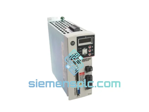
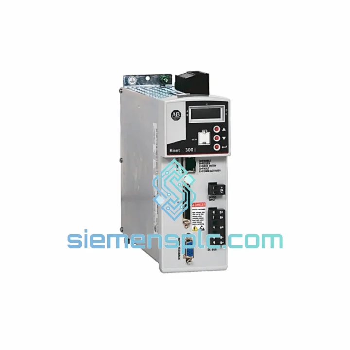
Allen-Bradley 2097-V34PR5-LM Servo Drive – Kinetix 300
Request verified availability, condition, replacement risk review, packing options and courier lead time for 2097-V34PR5-LM.
BrandAllen-Bradley
Part Number2097-V34PR5-LM
ConditionAvailability Check
Lead TimeRFQ Confirmation
DocumentsDatasheet / photos by RFQ
ShippingExport packing available
Auto-filled RFQ
2097-V34PR5-LM
Click Request Quote and the part number is inserted into the inquiry form automatically.
- Reply by email: [email protected]
- WhatsApp / Tel: +86 18359268345
- Mon-Sat 9:00-18:00 GMT+8
Procurement Data
Key Product Information
Core fields for model confirmation and RFQ routing. Detailed product narrative remains below.
- Brand
- Allen-Bradley
- Primary Part Number
- 2097-V34PR5-LM
- Product Type
- Servo Drive
- Series / Family
- Kinetix
- Country of Origin
- US
- Catalog Category
- Motor Drives
- Warranty
- 12 months from verified shipment date
Model confirmed for inquiry
2097-V34PR5-LM
Send quantity, destination and urgency. The RFQ form keeps this part number attached.
Request Quote
Product Overview
2097-V34PR5-LM: Closed-Loop Torque and Velocity Authority in a Self-Contained EtherNet/IP Servo Node
The Allen-Bradley 2097-V34PR5-LM is a 2.0 kW single-axis servo drive belonging to Rockwell Automation’s Kinetix 300 product family. Its architectural premise is straightforward: consolidate rectification, DC bus management, PWM inversion, and network communication into a single panel-mount enclosure rated IP20, while delegating trajectory computation to the host Logix controller over a standard 100 Mbps EtherNet/IP link. The result is a drive that occupies minimal DIN rail space yet participates fully in a coordinated multi-axis motion system without requiring a dedicated motion network or proprietary backplane.
In the context of a servo control loop, the 2097-V34PR5-LM owns the two innermost loops: current regulation and velocity regulation. Current loop execution occurs at the drive’s internal PWM switching period — nominally 8 kHz — giving a current loop bandwidth well above the mechanical resonance frequencies of most servo-coupled loads. The velocity loop runs at a subordinate rate, typically 4 kHz, and accepts velocity set-points either from the onboard position loop (when operating in position mode) or directly from the Logix controller via EtherNet/IP implicit messaging. The host controller’s position loop closes over the network at a Requested Packet Interval configurable between 1 ms and 4 ms, a range that accommodates both high-dynamic pick-and-place applications and lower-bandwidth web-tension or conveyor-tracking tasks on the same network segment.
Each axis is electrically independent: the 2097-V34PR5-LM has its own three-phase AC input terminals, its own internal rectifier, and its own DC bus capacitor bank. There is no shared bus topology. This means a fault on one axis — whether an overcurrent trip, an encoder loss, or a thermal shutdown — does not propagate to adjacent drives through a common DC rail. Panel designers can therefore treat each drive as an isolated power conversion node, simplifying fault isolation analysis and reducing the scope of safety-rated interlocks required per axis.
Real-time Stock & RFQ: [email protected] | WhatsApp: +86 18359268345
Technical Parameters
| Part Number | 2097-V34PR5-LM |
| Product Family | Kinetix 300 |
| Brand | Allen-Bradley (Rockwell Automation) |
| Rated Continuous Output Power | 2.0 kW |
| AC Input Voltage Range | 200–240 V AC, 3-Phase, ±10% |
| AC Input Frequency | 47–63 Hz |
| Continuous Output Current (RMS) | 5.0 A |
| Peak Output Current (RMS, ≤2 s) | 15.0 A |
| Internal DC Bus Voltage (nominal) | ~325 V DC at 240 V AC input |
| PWM Switching Frequency | 8 kHz (factory default) |
| Current Loop Update Rate | ≥8 kHz |
| Velocity Loop Update Rate | ≥4 kHz |
| Network Interface | EtherNet/IP, 100BASE-TX, IEEE 802.3 |
| Implicit Messaging RPI Range | 1–4 ms (Class 1 I/O connection) |
| Feedback Port | 15-pin HD-Sub D, single connector |
| Supported Feedback Types | 5 V differential incremental encoder; SinCos absolute encoder; Resolver |
| Logic Supply Voltage | 24 V DC, ±10%, external, isolated |
| Safe Torque Off (STO) | Hardwired dual-channel STO, SIL 2 / PLd per EN ISO 13849-1 |
| Internal Shunt Resistor | Included; external shunt terminal available |
| Operating Ambient Temperature | 0 °C to +50 °C (derate above 40 °C) |
| Storage Temperature | −40 °C to +85 °C |
| Relative Humidity | 5–95%, non-condensing |
| Enclosure / Protection Class | IP20, panel-mount |
| Mounting | DIN rail (EN 60715) or panel screw-mount |
| Certifications | UL 508C, cUL, CE (EN 61800-5-1, EN 61800-3 Cat. C2) |
| Approximate Unit Weight | 0.15 kg |
| HS Tariff Code | 8504.40 |
| Warranty | 12 months from verified shipment date |
Hardware Logical Analysis
The power stage of the 2097-V34PR5-LM is built around a three-phase IGBT inverter bridge driven by a dedicated DSP. The AC input is rectified by a six-pulse diode bridge, producing an unregulated DC bus that sits at approximately 325 V DC under nominal 240 V AC input conditions. A bank of electrolytic capacitors on the DC bus provides holdup energy sufficient to ride through input voltage interruptions of up to approximately 20 ms — a threshold that covers the majority of voltage sag events caused by upstream motor starting on shared distribution panels.
Regenerative Energy Management: During motor deceleration, kinetic energy from the load is returned to the DC bus through the IGBT bridge operating in synchronous rectification mode. When the bus voltage climbs above the shunt activation threshold (approximately 390 V DC), the onboard shunt transistor switches the internal braking resistor across the bus, dissipating excess energy as heat. The shunt circuit is rated for intermittent duty; applications with high-inertia loads or frequent deceleration cycles should connect an external braking resistor to the dedicated terminals to increase total dissipation capacity and prevent thermal derating of the internal resistor.
EMC Architecture: The AC input stage incorporates an integrated common-mode and differential-mode filter, designed to attenuate conducted emissions to EN 61800-3 Category C2 limits without requiring an external line filter in standard installations. On the motor output side, a common-mode choke is placed in series with the three motor phase conductors. This choke presents high impedance to the zero-sequence (common-mode) current components generated by the PWM switching transitions, reducing the magnitude of bearing currents that would otherwise flow through the motor shaft and races — a primary failure mechanism in PWM-driven servo motors operating at 8 kHz switching frequency. Shield termination lugs on the drive chassis provide a direct, low-inductance path for cable shield currents back to the drive’s PE terminal, preventing shield currents from coupling into the signal ground plane of the feedback interface.
Feedback Interface Signal Chain: The 15-pin HD-Sub feedback connector routes to three parallel signal conditioning circuits within the drive: a differential line receiver pair for 5 V incremental encoder signals (A, B, Z channels with quadrature decoding and index capture); a SinCos interpolation ASIC that digitizes the 1 V peak-to-peak sine and cosine signals from high-resolution absolute encoders to produce sub-micron position resolution; and a resolver excitation oscillator with synchronous demodulation circuitry that converts the resolver’s amplitude-modulated sine and cosine outputs into a digital position word. The active feedback path is selected automatically during drive initialization based on the motor data file downloaded from the Logix controller, eliminating manual hardware configuration.
Logic Power Architecture: The 24 V DC logic supply feeds the control board, the EtherNet/IP physical layer transceiver, and the feedback interface circuits through an isolated DC-DC converter internal to the drive. This isolation ensures that transients on the 24 V bus — common in panels where solenoid valves and contactors share the same 24 V rail — do not couple into the drive’s control circuitry. Critically, the logic supply remains active when the main AC contactor is open, allowing the Logix controller to poll drive fault registers, read encoder position, and execute diagnostic routines without energizing the motor power stage.
Safe Torque Off Implementation: The STO function is implemented as a dual-channel hardwired input that disables the gate drive signals to the IGBT bridge independently of the DSP firmware. Both channels must be de-energized simultaneously to achieve the STO state; a single-channel failure is detected by the drive’s safety logic and reported as a fault. This architecture meets SIL 2 per IEC 62061 and PLd per EN ISO 13849-1 without requiring a separate safety relay module in the E-stop circuit.
System Integration Benefits
- Studio 5000 Add-On Profile (AOP) compatibility: The drive’s certified AOP auto-populates all axis parameter tags, engineering unit scaling, and fault action tables in the Logix project tree. An integrator can complete axis configuration — including feedback type, travel limits, and torque limits — within a single dialog without referencing the drive’s parameter manual.
- Deterministic EtherNet/IP motion data delivery: Class 1 implicit messaging with DSCP QoS marking ensures motion set-point and feedback packets are prioritized over standard TCP/IP traffic on a managed switch. Measured jitter on a properly configured network is below 100 µs at a 1 ms RPI, meeting the timing requirements of most servo positioning applications.
- Independent axis fault containment: The isolated DC bus topology means a drive-level fault — overcurrent, overvoltage, encoder loss — does not affect the DC bus voltage of adjacent axes. Machine designers can implement per-axis fault responses without coordinating bus discharge sequences across multiple drives.
- STO integration without external safety relay: The dual-channel STO input allows the drive to participate in a SIL 2 E-stop circuit directly, reducing panel component count, wiring complexity, and the number of safety-rated components requiring periodic proof testing.
- Multi-feedback type support on a single connector: Incremental, SinCos absolute, and resolver feedback are all supported through the same 15-pin port. Mixed motor populations — for example, a machine line using resolver-based motors on high-temperature axes and SinCos absolute encoders on precision positioning axes — can be accommodated without additional feedback interface hardware.
- Onboard velocity and current loop auto-tuning: The drive’s auto-tuning routine, initiated from Logix Designer’s Motion Analyzer tool, injects a swept-frequency excitation signal into the velocity loop, measures the load’s frequency response, and computes bandwidth-optimized proportional and integral gains. The process completes in under 90 seconds and does not require manual Bode plot analysis or iterative gain adjustment.
- Fault code transparency to the Logix tag database: The drive maps its complete fault and warning register set into the Logix axis fault attribute table. Each entry includes a fault code, a fault description string, and a recommended corrective action — all accessible from the controller’s HMI tag database without opening a separate drive configuration tool.
- Absolute position retention across main power cycles: With the 24 V logic supply maintained, the drive retains the absolute encoder position register across main AC power interruptions. Machines with long or complex homing sequences benefit directly: planned shutdowns and E-stop events do not require a full homing cycle before resuming production.
Quality Assurance & Global Logistics
Units of the 2097-V34PR5-LM supplied through siemensplc.com are sourced as genuine Allen-Bradley / Rockwell Automation product. Each unit entering inventory is subject to a three-stage incoming inspection: label and catalog number verification against Rockwell’s published label format and date-code structure; firmware revision confirmation via the drive’s EtherNet/IP identity object (Class 0x01, Instance 0x01); and a functional power-on test that verifies DC bus charge-up behavior, 24 V logic supply regulation within ±5%, and EtherNet/IP port link establishment at 100 Mbps. Units that do not satisfy all three criteria are segregated and excluded from sale inventory.
Packaging is handled under ESD-safe procedures throughout. Each drive is placed in a conductive poly bag, nested in anti-static foam inserts, and sealed in a double-wall corrugated outer carton. A silica gel desiccant packet is included for shipments to destinations with high ambient humidity. Where original Rockwell factory packaging is available and intact, it is preserved and used as the primary container.
All shipments originate from Xiamen, China. Standard export carriers include DHL Express, FedEx International Priority, and UPS Worldwide Express, with typical door-to-door transit times of 3–5 business days to major industrial destinations in Europe, North America, the Middle East, and Southeast Asia. Export documentation prepared for every international shipment includes: commercial invoice with declared value, packing list with net and gross weights, HS code 8504.40 customs declaration, and a Certificate of Conformance. For orders requiring ECCN classification documentation or an end-user statement, these are prepared upon request prior to shipment dispatch.
A 12-month warranty covers verified manufacturing defects and drive failures occurring under normal operating conditions as defined in Rockwell publication 2097-UM001. Warranty claims are acknowledged within one business day; replacement or repair disposition is determined based on failure mode analysis and the buyer’s operational schedule.
Contact Information
Email: [email protected]
WhatsApp: +86 18359268345
Web: siemensplc.com
Location: Xiamen, China
© 2026 siemensplc.com. All rights reserved.
Ready to quote
[email protected]
Send This Part Number to Sales
RFQ workflow
Quality workflow ->
Confirmation Process
01Model confirmation
We check the full part number, brand, series and visible nameplate information before quotation.
02Availability reply
Sales confirms stock path, condition option, quantity and realistic lead time for export dispatch.
03Packing & courier
DHL, FedEx, UPS or buyer courier arrangements can be reviewed with packing requirements.
Continue sourcing
Browse full catalog ->
Related Automation Parts
Similar brand or category products for fast comparison and multi-item RFQ lists.
Allen-Bradley
RFQ Ready
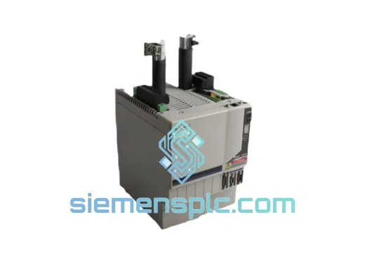
Allen-Bradley 2094-BC07-M05-M Servo Drive Module
Kinetix
Origin US
Servo Drive Module
Allen-Bradley
RFQ Ready
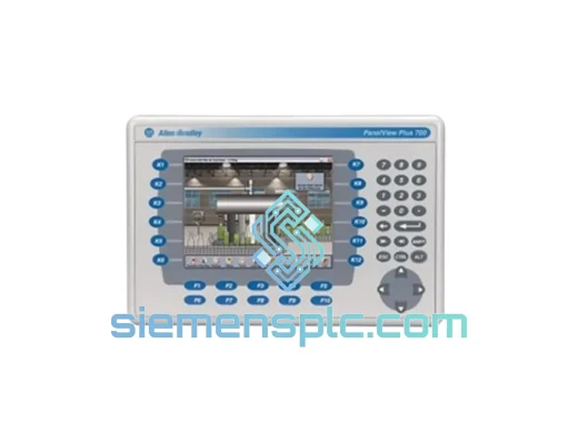
Allen-Bradley 2094-BC04-M03-M Servo Drive Module – Kinetix 6000
Kinetix
Origin US
Servo Drive Module
Allen-Bradley
RFQ Ready
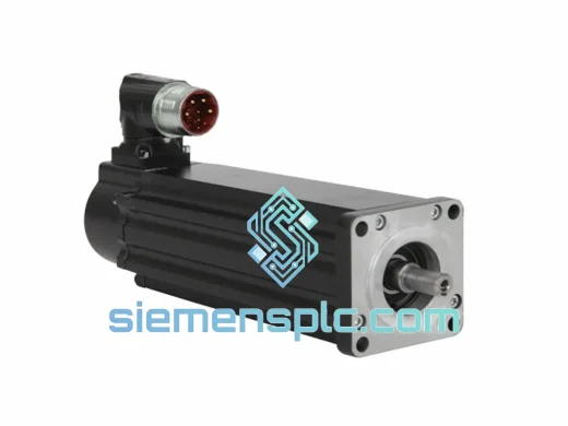
Allen-Bradley VPL-B0633M-CK12AA Servo Motor – Kinetix VPL
Kinetix
Origin US
Servo Motor