Allen-Bradley
In Stock OK
Allen-Bradley 2198-D057-ERS3 Servo Inverter – Kinetix 5700
Request verified availability, condition, replacement risk review, packing options and courier lead time for 2198-D057-ERS3.
BrandAllen-Bradley
Part Number2198-D057-ERS3
ConditionAvailability Check
Lead TimeRFQ Confirmation
DocumentsDatasheet / photos by RFQ
ShippingExport packing available
Auto-filled RFQ
2198-D057-ERS3
Click Request Quote and the part number is inserted into the inquiry form automatically.
- Reply by email: [email protected]
- WhatsApp / Tel: +86 18359268345
- Mon-Sat 9:00-18:00 GMT+8
Procurement Data
Key Product Information
Core fields for model confirmation and RFQ routing. Detailed product narrative remains below.
- Brand
- Allen-Bradley
- Primary Part Number
- 2198-D057-ERS3
- Product Type
- Servo Drive
- Series / Family
- Kinetix
- Country of Origin
- US
- Catalog Category
- Motor Drives
- Operating Temp.
- 0 °C to +50 °C (derate above 40 °C at 2%/°C)
- Warranty
- 12 months from date of shipment
Model confirmed for inquiry
2198-D057-ERS3
Send quantity, destination and urgency. The RFQ form keeps this part number attached.
Request Quote
Product Overview
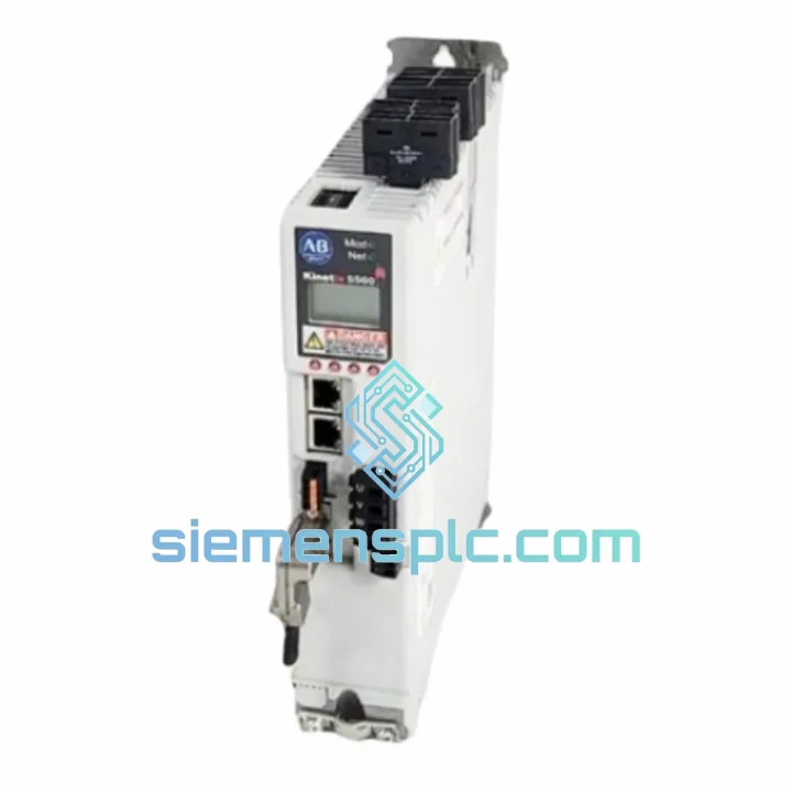
Allen-Bradley 2198-D057-ERS3: Dual-Axis Inverter Module in the Kinetix 5700 Servo Drive Platform
The 2198-D057-ERS3 is a dual-axis inverter module within Rockwell Automation’s Kinetix 5700 servo drive family. It operates from a shared DC bus architecture, accepting rectified DC from a compatible Kinetix 5700 power supply (such as the 2198-P070 or 2198-P141) and delivering independently regulated three-phase AC output to two servo motor axes simultaneously. Each axis is rated at 22 A RMS continuous and 57 A peak for a 3-second overload window, making this module applicable to medium-power servo axes in coordinated multi-axis machine designs.
The ERS3 firmware designation identifies the third major firmware generation for the Kinetix 5700 platform. This revision introduced native support for Rockwell Automation’s iTRAK intelligent track system and MagnaView linear transport, expanded CIP Safety integration, and refined the CIP Motion axis state machine for tighter synchronization across large axis counts. Compatibility requires Studio 5000 Logix Designer v32.00 or later and a ControlLogix 5580, CompactLogix 5380/5480, or GuardLogix 5580 controller with an active CIP Motion license.
Real-time Stock & RFQ: [email protected] | WhatsApp: +86 18359268345
Technical Parameters
| Parameter | Specification |
|---|---|
| Catalog Number | 2198-D057-ERS3 |
| Platform | Kinetix 5700 |
| Module Classification | Dual-Axis Inverter |
| Firmware Generation | ERS3 (Studio 5000 v32+ required) |
| Continuous Output Current (per axis) | 22 A RMS |
| Peak Output Current (per axis) | 57 A (3 s overload) |
| DC Bus Input Voltage Range | 264–678 V DC (nominal 650 V DC) |
| Output Voltage | 0–480 V AC, 3-phase PWM |
| PWM Switching Frequency | 4 kHz / 8 kHz (selectable per axis) |
| Communication Interface | EtherNet/IP, dual-port, DLR-capable |
| CIP Motion Update Rate | ≤ 1 ms (controller-dependent) |
| Supported Feedback Protocols | Hiperface DSL, EnDat 2.2, Resolver, Incremental TTL/SIN-COS |
| Integrated Safety Functions | STO, SS1, SLS — IEC 62061 SIL 2 / ISO 13849 PLd |
| Safety Communication | CIP Safety over EtherNet/IP |
| Enclosure Rating | IP20 (panel-mount installation) |
| Operating Temperature | 0 °C to +50 °C (derate above 40 °C at 2%/°C) |
| Storage Temperature | −40 °C to +70 °C |
| Relative Humidity | 5–95%, non-condensing |
| Vibration Resistance | 2 g, 10–500 Hz (IEC 60068-2-6) |
| Shock Resistance | 15 g, 11 ms half-sine (IEC 60068-2-27) |
| Approximate Dimensions (H × W × D) | 380 × 90 × 260 mm |
| Approximate Weight | 5.5 kg |
| Regulatory Certifications | UL, cUL, CE (LVD + EMC), RCM |
| Warranty | 12 months from date of shipment |
Hardware Logical Analysis
The 2198-D057-ERS3 is built around a shared DC bus topology that fundamentally changes the energy accounting of a multi-axis servo system. Rather than each axis rectifying its own AC supply independently, all Kinetix 5700 inverter modules on a common bus segment draw from a single rectified DC rail. When one axis decelerates and its motor operates as a generator, the resulting regenerative energy is injected back onto the DC bus and is immediately available to any simultaneously accelerating axis. In practice, this inter-axis energy exchange reduces the net demand on the AC supply and can lower peak current draw by 20–35% in coordinated motion profiles, depending on the duty cycle overlap between axes.
Each of the two inverter channels uses an independent IGBT bridge with dedicated gate-drive circuitry. The gate-drive stage incorporates desaturation detection: if an IGBT enters the linear region due to an overcurrent event, the gate drive detects the collector-emitter voltage rise within approximately 2 µs and initiates a controlled shutdown, preventing thermal runaway without requiring an external current-sense shunt in the motor cable. This on-chip protection reduces the fault-to-shutdown latency compared to external overcurrent relay schemes.
The feedback interface supports Hiperface DSL, a single-cable protocol that multiplexes power, position data, and diagnostic information over the motor power cable shield. This eliminates the separate encoder cable run, reducing wiring harness mass and the number of connector terminations in the cabinet — a measurable advantage in high-axis-count machines where cable management is a recurring integration cost. The DSL interface operates at 9.375 Mbit/s with 32-bit absolute position resolution per revolution, providing sub-arc-second angular feedback without interpolation error accumulation across power cycles.
EMC performance is addressed at the PCB layout level. The DC bus conductors and the motor output conductors are routed on separate PCB layers with a ground plane interposed, reducing capacitive coupling between the high-dV/dt switching node and the low-level feedback signal traces. The module’s metal enclosure provides a Faraday shield for the internal electronics, and the EtherNet/IP ports include common-mode chokes on the magnetics to suppress conducted emissions on the network cable — relevant in environments with variable-frequency drives or welding equipment operating nearby.
The integrated safety core runs on a dedicated microcontroller that is electrically isolated from the main motion processor. STO is implemented by removing gate-drive power from both IGBT bridges simultaneously via two independent hardware paths, satisfying the dual-channel requirement of IEC 62061 SIL 2. The safety core monitors its own supply voltage and the integrity of the STO input signals at a diagnostic test rate of 100 ms, reporting any discrepancy to the CIP Safety controller before the next machine cycle.
System Integration Benefits
- Deterministic CIP Motion Synchronization: The EtherNet/IP interface supports CIP Motion with configurable update periods down to 250 µs (controller-limited). All axes on the same controller share a synchronized time base via IEEE 1588 PTP, enabling electronic gearing and camming with axis-to-axis jitter below 1 µs — a prerequisite for register control in printing and converting applications.
- Reduced Panel Footprint: Two servo axes occupy a single 90 mm module width. In a 12-axis machine, this translates to six inverter modules versus twelve single-axis alternatives, freeing approximately 540 mm of DIN rail and reducing enclosure depth requirements.
- Unified Diagnostic Transparency: The module reports over 40 fault and warning codes via CIP Motion attributes, accessible in real time through Studio 5000 or any EtherNet/IP diagnostic tool. Fault codes include axis-specific overcurrent, feedback loss, bus undervoltage, and thermal derating events — each with a timestamp referenced to the controller’s coordinated system time.
- Auto-Configuration via Add-On Profiles: Importing the Kinetix 5700 AOP into Studio 5000 automatically populates axis parameters, feedback scaling, and safety configuration templates. Manual parameter entry is eliminated, reducing commissioning errors and cutting typical axis bring-up time from hours to minutes.
- Scalable Safety Architecture: STO, SS1, and SLS functions are configurable per axis independently. In a machine with mixed safety zones, axes in a low-risk zone can remain powered while axes in a high-risk zone execute STO — without stopping the entire drive bus or requiring additional safety relays.
- iTRAK and Linear Transport Compatibility: ERS3 firmware includes the motion instruction set required for independent mover control on iTRAK track systems. Each mover is treated as a virtual axis within the Logix project, with position feedback derived from the track’s linear encoder array rather than a motor-mounted encoder.
- Network Redundancy via DLR: The dual EtherNet/IP ports support Device Level Ring topology. A single cable break anywhere in the ring does not interrupt motion communication; the network reconfigures within 3 ms, below the fault detection threshold of most motion applications.
- Energy Monitoring and Reporting: The module exposes DC bus voltage, per-axis output current, and internal temperature as CIP attributes, enabling the Logix controller to log energy consumption data for OEE reporting or predictive maintenance algorithms without additional instrumentation hardware.
Quality Assurance & Global Logistics
Every 2198-D057-ERS3 unit offered through siemensplc.com is sourced as genuine Allen-Bradley / Rockwell Automation product. Prior to listing, each unit undergoes a structured pre-shipment inspection protocol: visual examination of the housing, connector pins, and label integrity; cross-referencing of date codes and PCB revision markings against Rockwell Automation factory documentation; and a functional power-on verification where test equipment permits. Units are stored in a climate-controlled warehouse in Xiamen, China, maintained at 18–25 °C with relative humidity below 60%, in anti-static bags with desiccant packs inside ESD-safe foam-lined cartons.
Shipments originate from Xiamen, Fujian Province, China. Standard export documentation includes a commercial invoice, packing list, and certificate of origin. DHL Express and FedEx International Priority are the primary carriers for time-sensitive orders, with typical transit times of 3–5 business days to Europe, 4–6 business days to North America, and 2–4 business days to Southeast Asia. Sea freight consolidation is available for bulk orders. All units ship with a 12-month warranty covering manufacturing defects and verified functional failures under normal operating conditions. Warranty claims are processed within 5 business days of receipt of the returned unit, with replacement or credit issued accordingly.
Contact Information
Email: [email protected]
WhatsApp: +86 18359268345
Web: siemensplc.com
Location: Xiamen, China
© 2026 siemensplc.com. All rights reserved.
Ready to quote
[email protected]
Send This Part Number to Sales
RFQ workflow
Quality workflow ->
Confirmation Process
01Model confirmation
We check the full part number, brand, series and visible nameplate information before quotation.
02Availability reply
Sales confirms stock path, condition option, quantity and realistic lead time for export dispatch.
03Packing & courier
DHL, FedEx, UPS or buyer courier arrangements can be reviewed with packing requirements.
Continue sourcing
Browse full catalog ->
Related Automation Parts
Similar brand or category products for fast comparison and multi-item RFQ lists.