Allen-Bradley
RFQ Ready
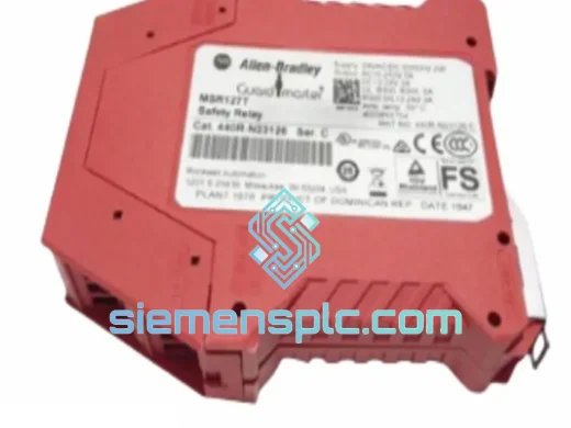
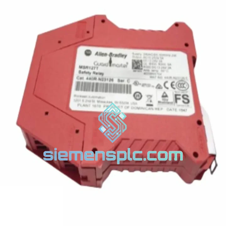
Allen-Bradley 440R-N23126 Safety Relay – Guardmaster 440R
Origin US
Safety Relay
Request verified availability, condition, replacement risk review, packing options and courier lead time for MSR310P.
Click Request Quote and the part number is inserted into the inquiry form automatically.
Core fields for model confirmation and RFQ routing. Detailed product narrative remains below.
The Allen-Bradley MSR310P is a dual-channel safety relay module engineered for integration into machine safety control loops where functional safety standards IEC 62061 and EN ISO 13849-1 impose mandatory performance requirements. Its primary role is to monitor the integrity of safety-rated input devices — emergency stop pushbuttons, interlocked guard doors, enabling devices, and two-hand control stations — and to execute a controlled, de-energize-to-safe output switching action upon detection of any input channel fault, wiring discrepancy, or deliberate actuation.
Within a safety control loop, the MSR310P occupies the logic evaluation layer between the input device (sensor/actuator) and the final switching element (contactor, valve, drive enable). It performs cross-channel monitoring by continuously comparing the state of both input channels. Any asymmetry exceeding the module’s internal timing window — typically caused by a welded contact, broken wire, or simultaneous dual-channel fault — is classified as a discrepancy and forces the safety outputs to the de-energized state without relying on the host PLC for intervention. This architecture ensures that the safety function remains intact even when the supervisory control system is in a faulted or unpowered state.
The module supports both automatic and manual (monitored) reset modes. In monitored reset mode, the reset input must transition from low to high and back to low before the safety outputs can re-energize, preventing unintended restart after a safety event — a requirement explicitly stated in ISO 13849-1 for Category 3 and Category 4 architectures. The MSR310P achieves up to Category 4 / Performance Level e (PLe) and Safety Integrity Level 3 (SIL 3), making it applicable to the highest-risk machine safety scenarios defined by current European and international standards.
Real-time Stock & RFQ: [email protected] | WhatsApp: +86 18359268345
| Parameter | Value |
|---|---|
| Manufacturer | Allen-Bradley / Rockwell Automation |
| Part Number | MSR310P |
| Module Type | Dual-Channel Safety Relay |
| Supply Voltage | 24 V DC / 24–240 V AC (universal input variant) |
| Input Channels | 2 (dual-channel monitored) |
| Safety Output Contacts | 3 × NO (normally open) instantaneous |
| Auxiliary Output | 1 × NC (normally closed) signaling |
| Max. Switching Voltage (Outputs) | 250 V AC / 24 V DC |
| Max. Switching Current (Outputs) | 6 A per contact |
| Response Time (Input → Output OFF) | ≤ 20 ms |
| Safety Category (EN ISO 13849-1) | Up to Category 4 / PLe |
| SIL Rating (IEC 62061) | SIL 3 |
| PFH (Probability of Dangerous Failure/hr) | < 1 × 10⁻⁸ /h |
| Operating Temperature | 0 °C to +55 °C |
| Storage Temperature | −25 °C to +70 °C |
| Relative Humidity | 5–95 % (non-condensing) |
| Mounting | 35 mm DIN rail (EN 60715) |
| Housing Width | 22.5 mm |
| Enclosure Rating | IP40 (module body) |
| Weight | approx. 200 g |
| Certifications | CE, UL, cUL, TÜV Rheinland |
| Applicable Standards | IEC 62061, EN ISO 13849-1, IEC 60947-5-1 |
| Warranty | 12 months from shipment date |
Cross-Channel Discrepancy Detection Circuit: The MSR310P implements a hardware-level cross-channel comparator that monitors both input channels simultaneously at a sampling rate independent of any external processor. The comparator evaluates the temporal relationship between channel A and channel B state transitions. If both channels do not transition within a defined synchronization window (typically configurable or fixed at ≤ 500 ms depending on variant), the internal logic classifies the event as a discrepancy fault and latches the output relay coils in the de-energized state. This latch can only be cleared by a valid reset sequence, preventing automatic restart.
Forced-Guided Relay Contacts (Positive-Mode Operation): The output relay assembly uses mechanically linked (force-guided) contacts per IEC 60947-5-1 Annex L. The mechanical coupling between the NO safety contacts and the NC auxiliary contact ensures that if any NO contact welds closed, the NC auxiliary contact is physically prevented from closing. This property allows the upstream safety controller or PLC to verify relay contact integrity on every reset cycle by reading the NC feedback loop — a mandatory diagnostic measure for achieving Category 4 architectures.
EMC Design and Noise Immunity: The input circuit incorporates RC filtering and transient voltage suppression (TVS) diodes on both input channels, providing immunity to conducted disturbances per IEC 61000-4-4 (electrical fast transient, 2 kV) and IEC 61000-4-5 (surge, 1 kV). The relay coil driver stage uses a flyback suppression diode to eliminate inductive kickback that could otherwise couple noise into adjacent signal wiring in dense DIN rail assemblies. The module’s PCB layout follows IEC 61000-4-3 radiated immunity guidelines, with ground planes separating high-voltage switching nodes from low-voltage logic circuitry.
Internal Watchdog and Self-Test Logic: An internal watchdog circuit periodically exercises the output relay coils during the de-energized state to verify coil continuity and driver transistor integrity. This self-test is transparent to the connected load and completes within the module’s response time budget. Any failure detected during self-test results in a permanent fault state, indicated by the module’s diagnostic LED, and prevents re-energization until the fault is cleared by power cycling — consistent with Type B safety component behavior under IEC 61508.
Reset Input Monitoring: In monitored manual reset mode, the reset input circuit requires a specific pulse width (rising edge followed by falling edge within a defined window) to validate a genuine operator reset action. This prevents a shorted or stuck reset button from allowing continuous automatic restart — a failure mode that would otherwise defeat the safety function at the system level.
Every Allen-Bradley MSR310P unit supplied through siemensplc.com is sourced from verified supply channels and subjected to a structured incoming inspection protocol before dispatch. Physical inspection covers label authenticity, date code consistency, connector pin integrity, and housing condition. Functional verification confirms relay coil resistance, contact continuity across all NO and NC outputs, and LED indicator operation under applied supply voltage. Batch traceability records — including supplier documentation, date codes, and inspection results — are retained and available upon request for quality audit purposes.
Anti-counterfeit verification is performed on all Allen-Bradley branded components. This includes UV label inspection, holographic seal verification, and cross-referencing of date codes against known production windows. Units that do not pass all verification steps are quarantined and not offered for sale.
Logistics operations are based in Xiamen, China — a major international port city with direct air freight connections to major industrial hubs in Europe, Southeast Asia, the Middle East, and the Americas. Standard dispatch lead time is 3–7 business days from order confirmation. Express air freight options (DHL, FedEx, UPS) are available for urgent requirements, with typical transit times of 3–5 business days to most destinations. Sea freight consolidation is available for large-volume orders. All shipments include commercial invoice, packing list, and certificate of conformity. Export documentation for customs clearance is prepared in accordance with destination country requirements.
A 12-month warranty covers all units from the shipment date. Dead-on-arrival (DOA) replacement is processed within 7 business days of confirmed fault report. Warranty claims require photographic evidence of the fault condition and the original shipping documentation.
Email: [email protected]
WhatsApp: +86 18359268345
Web: siemensplc.com
Location: Xiamen, China
© 2026 siemensplc.com. All rights reserved.
We check the full part number, brand, series and visible nameplate information before quotation.
Sales confirms stock path, condition option, quantity and realistic lead time for export dispatch.
DHL, FedEx, UPS or buyer courier arrangements can be reviewed with packing requirements.
Similar brand or category products for fast comparison and multi-item RFQ lists.