Allen-Bradley
RFQ Ready
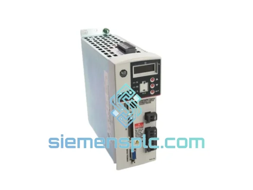
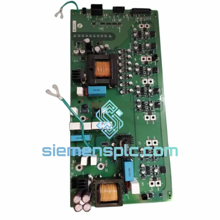
Allen-Bradley 20AD3P4A0AYNNNC0 Variable Frequency Drive
PowerFlex
Origin US
Variable Frequency Drive
Request verified availability, condition, replacement risk review, packing options and courier lead time for PN-200960.
Click Request Quote and the part number is inserted into the inquiry form automatically.
Core fields for model confirmation and RFQ routing. Detailed product narrative remains below.
The Allen-Bradley PN-200960 is a factory-grade inverter power board engineered as a direct sub-assembly within Rockwell Automation variable frequency drive (VFD) platforms. Its primary function is the conversion of rectified DC bus voltage into a precisely timed, pulse-width-modulated (PWM) AC output, delivered through isolated IGBT gate drive signals to the power switching stage. In closed-loop motor control architectures, this board sits at the intersection of the control processor and the power semiconductor stack — making its signal integrity and thermal stability directly deterministic of drive output quality.
Unlike generic replacement boards, the PN-200960 is designed to maintain gate signal propagation delays within the nanosecond-level tolerances required by Rockwell’s proprietary flux vector control algorithms. Any deviation in gate timing introduces dead-time asymmetry, which manifests as harmonic distortion in the motor current waveform and, in severe cases, shoot-through faults in the IGBT bridge. The PN-200960’s gate driver circuitry is matched to the specific IGBT module characteristics of the target drive frame, ensuring that turn-on and turn-off dV/dt slopes remain within the IGBT’s safe operating area (SOA) across the full operating temperature range of -10°C to +55°C.
The board integrates DC bus voltage sensing, desaturation detection, and fault latch logic — three hardware-level protection mechanisms that operate independently of the main drive CPU. This architecture ensures that overcurrent and short-circuit events are responded to within 2–5 µs, well below the propagation latency of any firmware-based protection routine. The result is a protection response time that is deterministic and immune to CPU task scheduling jitter.
For maintenance engineers managing Allen-Bradley PowerFlex drive fleets in continuous-process industries — including petrochemical, mining, water treatment, and heavy manufacturing — the PN-200960 represents a board-level replacement strategy that restores full drive functionality without requiring complete drive chassis replacement. Mean time to repair (MTTR) is reduced from multi-day lead times for new drive procurement to same-shift restoration when a verified spare is available on-site.
Real-time Stock & RFQ: [email protected] | WhatsApp: +86 18359268345
| Manufacturer | Allen-Bradley (Rockwell Automation) |
| Part Number / SKU | PN-200960 |
| Component Classification | Inverter Power Board / Gate Drive Sub-Assembly |
| Target Platform | Rockwell Automation Variable Frequency Drive (VFD) Series |
| Primary Function | DC bus-to-AC PWM conversion; isolated IGBT gate signal generation |
| Gate Drive Isolation | Opto-coupler or transformer-based galvanic isolation per IGBT channel |
| Protection Functions | Desaturation detection, DC bus overvoltage latch, short-circuit fault response ≤5 µs |
| Operating Temperature | -10°C to +55°C (ambient, with rated airflow) |
| Storage Temperature | -40°C to +85°C |
| PCB Form Factor | OEM sub-assembly PCB, direct drop-in replacement |
| Compliance | CE, RoHS (per original OEM specification) |
| Condition Available | New / Surplus New (specify at inquiry) |
| Warranty | 12 months from date of dispatch |
| Lead Time (In-Stock) | Ships within 1–3 business days from Xiamen, China |
Galvanic Isolation Architecture: Each IGBT gate channel on the PN-200960 is driven through a dedicated isolation stage — either a high-speed opto-coupler (typical propagation delay <500 ns) or a coreless transformer driver — that provides a minimum of 1,500 Vrms isolation between the low-voltage control domain and the high-voltage power domain. This isolation is not merely a safety measure; it is a functional requirement for preventing common-mode noise injected by IGBT switching transients (dV/dt up to 10 kV/µs) from corrupting the PWM reference signals on the control side of the board.
EMC Design and Noise Immunity: The board layout follows a strict ground-plane partitioning strategy: the analog signal ground, digital logic ground, and power return paths are separated at a single-point star ground to prevent high-frequency switching currents from coupling into sensitive measurement circuits. Decoupling capacitors are placed within 2 mm of each gate driver IC supply pin, maintaining supply rail impedance below 0.1 Ω at switching frequencies up to 16 kHz. Ferrite beads on gate drive output traces suppress high-frequency ringing without introducing excessive gate resistance that would slow IGBT switching transitions.
Desaturation Detection Logic: The PN-200960 implements active desaturation monitoring on each IGBT channel. During the on-state, the collector-emitter voltage (VCE) is continuously sampled through a high-voltage diode clamp network. If VCE exceeds the desaturation threshold — indicating an overcurrent condition that is driving the IGBT out of saturation — the gate driver immediately pulls the gate low through a dedicated fast turn-off path (separate from the normal PWM turn-off path) and latches the fault. This two-path gate drive topology (normal turn-off via gate resistor, fault turn-off via direct clamp) allows the protection response to be optimized independently of the PWM switching speed.
Thermal Management Interface: The power dissipation of the gate driver ICs and bootstrap diode networks is managed through direct thermal contact with the drive chassis heatsink via thermally conductive interface pads. The board’s component placement concentrates heat-generating devices along the heatsink-contact edge, minimizing thermal resistance from junction to case. This design keeps gate driver junction temperatures within datasheet limits even at maximum PWM frequency and ambient temperature.
Every Allen-Bradley PN-200960 dispatched from our Xiamen, China facility passes a documented four-stage inspection protocol before release. Visual inspection confirms PCB trace integrity, solder joint quality, and absence of mechanical damage or corrosion. Electrical bench verification checks gate driver supply rail stability, isolation resistance between control and power domains, and fault latch circuit continuity. Units sourced from authorized AB distribution channels retain full OEM certification traceability — CE marking and RoHS compliance documentation are available upon request.
Logistics from Xiamen are executed via DHL Express, FedEx International Priority, and UPS Worldwide, with typical transit times of 3–5 business days to Europe, North America, and Southeast Asia. All shipments include a commercial invoice, packing list, certificate of origin, and inspection certificate as standard documentation. For bulk MRO contracts, sea freight consolidation is available with 15–25 day transit. Export compliance screening is applied to all orders in accordance with applicable trade regulations. A 12-month warranty covers all units against manufacturing defects from the date of dispatch.
Email: [email protected]
WhatsApp: +86 18359268345
Web: siemensplc.com
Location: Xiamen, China
© 2026 siemensplc.com. All rights reserved.
We check the full part number, brand, series and visible nameplate information before quotation.
Sales confirms stock path, condition option, quantity and realistic lead time for export dispatch.
DHL, FedEx, UPS or buyer courier arrangements can be reviewed with packing requirements.
Similar brand or category products for fast comparison and multi-item RFQ lists.