Applied Materials
RFQ Ready
Applied Materials NITRIDE550-0021-39748 CVD Blocker Plate
Genuine OEM Supply
Origin US
CVD Chamber Component
Request verified availability, condition, replacement risk review, packing options and courier lead time for AS00800-10-1.
Click Request Quote and the part number is inserted into the inquiry form automatically.
Core fields for model confirmation and RFQ routing. Detailed product narrative remains below.
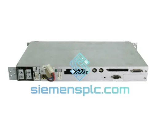
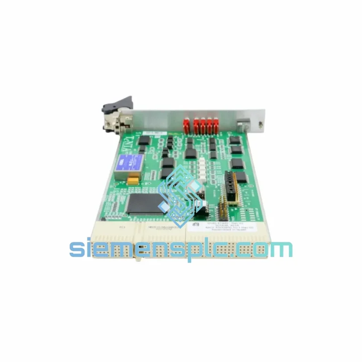
The Applied Materials AS00800-10-1 (field-service catalog reference: 0190-47445; assembly designations: SG25SA-P01U3 / SGMP-01U314M) is a multi-layer printed circuit board assembly engineered for precision analog and digital signal conditioning within Applied Materials chemical vapor deposition (CVD) and physical vapor deposition (PVD) process tool platforms. This board occupies a deterministic position in the process control hierarchy: it interfaces between the tool’s main controller backplane and the gas delivery / pressure management subsystem, translating high-level process recipes into low-latency actuator commands while simultaneously aggregating sensor feedback for closed-loop regulation.
In semiconductor fabrication environments operating at sub-10 nm nodes, the tolerance budget for signal drift, ground-loop noise, and command latency is effectively zero. The AS00800-10-1 addresses this constraint through a combination of differential signal routing, on-board galvanic isolation stages, and a regulated DC power architecture that maintains rail stability across the full thermal envelope of the process chamber enclosure. The board is validated for deployment in AMAT Centura, Producer SE, and Endura mainframe platforms, as well as MKS Instruments gas delivery subsystems cross-referenced under part number A 10 TTT.
Real-time Stock & RFQ: [email protected] | WhatsApp: +86 18359268345
| Parameter | Specification |
|---|---|
| Manufacturer | Applied Materials (AMAT) |
| Primary Part Number | AS00800-10-1 |
| Field-Service P/N | 0190-47445 |
| Assembly Reference | SG25SA-P01U3 / SGMP-01U314M |
| MKS Cross-Reference | A 10 TTT |
| Component Classification | PCB Assembly — Signal Conditioning & I/O Interface |
| Supply Voltage | +5 VDC / ±15 VDC (OEM backplane-supplied) |
| Logic Interface | TTL-compatible digital I/O; differential analog input channels |
| Isolation Architecture | Opto-isolated digital lines; transformer-coupled analog paths |
| Operating Temperature | 0 °C to +55 °C (ambient, forced-air cooled enclosure) |
| Storage Temperature | −25 °C to +70 °C |
| Humidity (Operating) | 10 % to 90 % RH, non-condensing |
| Board Form Factor | OEM card-cage format; single-slot insertion |
| PCB Layer Count | Multi-layer (≥6 layers, impedance-controlled) |
| Connector Interface | OEM-specific edge connector + auxiliary I/O headers |
| Weight (bare board) | ~20 g |
| Compliance | RoHS, SEMI S2/S8, ESD ANSI/ESD S20.20 |
| Warranty | 12 months from date of shipment |
The AS00800-10-1 board architecture is structured around three functional domains that operate concurrently without mutual interference: the digital command decode stage, the analog sensor aggregation stage, and the power conditioning stage.
Digital Command Decode Stage: Incoming process commands from the tool controller arrive via a TTL-level parallel bus. The board’s decode logic — implemented in a combination of programmable logic and discrete gate arrays — latches command words on the rising edge of the system clock, validates parity, and drives the appropriate actuator output lines within a deterministic propagation delay. This architecture eliminates the variable latency inherent in interrupt-driven software stacks, which is a critical requirement when controlling mass flow controllers (MFCs) where a 10 ms command slip can produce measurable deposition non-uniformity across a 300 mm wafer.
Analog Sensor Aggregation Stage: Pressure transducer outputs and MFC feedback signals enter the board through transformer-coupled differential input stages. The transformer coupling provides galvanic isolation rated to withstand the common-mode voltage transients generated when process chamber RF power (typically 13.56 MHz, 1–10 kW) couples into the chamber ground plane. After isolation, signals pass through precision instrumentation amplifiers with gain-error trimmed to ±0.05 % at the factory, feeding a successive-approximation ADC. The digitized values are time-stamped and forwarded to the controller backplane at a fixed sample rate, preserving the temporal integrity required for model-based process control algorithms.
Power Conditioning Stage: The board derives its operating rails from the backplane supply through an on-board DC-DC converter topology that provides line and load regulation better than ±1 %. A dedicated low-dropout regulator supplies the analog reference voltage, decoupled from the digital switching noise through a multi-stage LC filter network. This separation of analog and digital power domains is the primary mechanism by which the board achieves its specified signal-to-noise ratio on the analog input channels — a parameter that directly determines the minimum detectable pressure deviation in the process chamber.
EMC Design: The PCB stack-up places dedicated ground planes between every signal layer, providing a continuous return path that suppresses both radiated emissions and susceptibility to external RF fields. Critical analog traces are routed with controlled impedance (50 Ω ± 10 %) and guarded by grounded copper pours. The board passes SEMI S2 electromagnetic compatibility requirements without external shielding, which simplifies installation in card-cage environments where shielded enclosures are impractical.
Every AS00800-10-1 unit dispatched from our Xiamen, China facility undergoes a structured incoming inspection protocol before it is offered for sale. Visual inspection is performed against OEM reference imagery under controlled lighting, with particular attention to solder joint integrity, component seating, and connector contact condition. Part-number labels and date codes are verified against the OEM bill of materials. Where functional test capability is available, boards are powered on a bench fixture that replicates the backplane supply voltages and exercises the digital I/O and analog input channels against known reference signals.
Packaging follows ANSI/ESD S20.20 requirements: boards are placed in conductive foam carriers, sealed in metallized static-shielding bags with humidity indicator cards, and packed in double-wall corrugated cartons with foam-in-place cushioning. This packaging specification is designed to survive the mechanical shock and vibration profiles of international air freight without damage to the PCB assembly or its connectors.
Shipping is executed via DHL Express, FedEx International Priority, or UPS Worldwide Express, with typical transit times of 3–5 business days to North America and Europe, and 2–4 business days to Southeast Asia. Commercial invoice, packing list, and Certificate of Conformance are included with every shipment. Export classification is ECCN EAR99 for most destinations; buyers are responsible for verifying import requirements in their jurisdiction. EXW Xiamen and CIF destination terms are both available. In-stock units ship within 1–3 business days of order confirmation.
A 12-month warranty covers defects in materials and workmanship from the date of shipment. Warranty claims are processed with a target response time of 48 business hours. Replacement units are dispatched before the defective unit is returned, minimizing tool downtime for customers with active production schedules.
Email: [email protected]
WhatsApp: +86 18359268345
Web: siemensplc.com
Location: Xiamen, China
© 2026
We check the full part number, brand, series and visible nameplate information before quotation.
Sales confirms stock path, condition option, quantity and realistic lead time for export dispatch.
DHL, FedEx, UPS or buyer courier arrangements can be reviewed with packing requirements.
Similar brand or category products for fast comparison and multi-item RFQ lists.