Bently Nevada
RFQ Ready
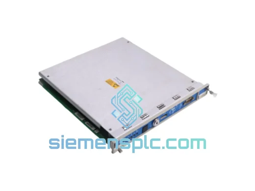
Bently Nevada 3500/94M 184826-01 Communications Gateway
3500 Series
Origin US
Communications Gateway Module
Request verified availability, condition, replacement risk review, packing options and courier lead time for 3077-755A.
Click Request Quote and the part number is inserted into the inquiry form automatically.
Core fields for model confirmation and RFQ routing. Detailed product narrative remains below.
The 3500 Series Machinery Protection System from Bently Nevada is the industry reference for API 670-compliant continuous monitoring of critical rotating machinery — gas turbines, steam turbines, centrifugal compressors, and large boiler feed pumps. Within this platform, measurement accuracy is not determined solely by the monitor card’s analog-to-digital converter. Every passive and active element between the transducer output terminal and the ADC input pin contributes to — or subtracts from — the fidelity of the measurement. The three-component assembly comprising part numbers 3077-755A, 9907-147N, and 5501-303L constitutes the complete field-to-rack interface layer: the electrical boundary at which transducer field wiring terminates, is conditioned, and is presented to the 3500 rack in a form that the monitor card can process with full amplitude and phase accuracy.
The 3077-755A is the field junction module. It accepts multi-channel transducer wiring — eddy-current proximity probes operating on the Bently Nevada 3300 XL driver standard at −24 VDC bias, velocity transducers with 4–20 mA or mV/(in/s) output formats, and IEPE or charge-mode piezoelectric accelerometers — and applies passive impedance matching and cable capacitance compensation to each channel independently. No active gain stage is present in the signal path. This passive architecture has a direct and measurable consequence for phase fidelity: without an active element, there is no frequency-dependent phase distortion between the transducer output and the monitor card input. For synchronous vibration analysis — specifically 1× vector measurement used in balancing calculations on large turbomachinery — phase angle accuracy of ±1° is a functional requirement. The passive FCI architecture preserves this accuracy without compromise across the full measurement bandwidth.
The 9907-147N termination board provides the mechanical and electrical landing geometry at the rack boundary. It enforces the differential pin mapping between the field cable and the 3500 monitor card’s input stage, routing each channel’s positive conductor, negative conductor, and shield drain through controlled-impedance PCB traces that suppress capacitive crosstalk between adjacent channels at the termination point. The revision suffix encoded in the 9907-147N part number reflects PCB layout changes that affect pin assignments. Mixing revision levels within a rack produces channel swaps that the monitor card’s self-test routines cannot detect — because the monitor card verifies signal presence and amplitude, not channel identity. A channel swap means the monitor card’s alarm setpoints for Channel 1 are applied to the transducer physically wired to Channel 2, creating a protection gap that is only discoverable through a full loop check with the machine at speed.
The 5501-303L cable assembly bridges the field junction module and the termination board with a shielded, impedance-controlled interconnect. Its drain wire is bonded at the rack end only. This single-point grounding topology is the correct EMC architecture for the electrical environment in which the 3500 system is deployed. Bonding the shield at both ends creates a closed conductive loop that functions as a secondary winding in the presence of magnetic flux from adjacent power cables. In installations co-located with variable-frequency drives operating at switching frequencies of 2 kHz to 16 kHz, circulating currents in a dual-bonded shield produce sidebands in the vibration spectrum at non-synchronous frequencies that can obscure early-stage bearing defect signatures at 3× to 7× running speed. The single-point bond eliminates the closed loop, allowing the shield to function as a Faraday barrier without becoming a noise injection path into the measurement channel.
Sourcing this assembly as a matched, revision-consistent set from a verified supply chain is a functional requirement, not a procurement preference. The three components are designed and validated as an integrated signal path. Independent sourcing from multiple distributors with different inventory ages introduces revision-mismatch risk that cannot be resolved without rack disassembly — a constraint that is unacceptable during a plant turnaround where commissioning time is measured in hours, not days.
Real-time Stock & RFQ: [email protected] | WhatsApp: +86 18359268345
| Primary Part Number | 3077-755A |
| Associated Part Numbers | 9907-147N (Termination Board) / 5501-303L (Cable Assembly) |
| Brand | Bently Nevada (Baker Hughes) |
| Product Series | FCI GF Series |
| Compatible Rack Platform | Bently Nevada 3500 Series Machinery Protection System |
| Module Function | Multi-channel passive transducer signal conditioning and field-to-rack interconnect |
| Supported Transducer Types | Eddy-current proximity probes (3300 XL standard), velocity transducers, IEPE accelerometers, charge-mode accelerometers |
| Proximity Probe Bias Voltage | −24 VDC nominal, supplied by monitor card through FCI signal path |
| Proximity Probe Scale Factor | 200 mV/mil (7.87 V/mm), preserved through passive FCI path without active gain stage |
| Velocity Input Format | 4–20 mA or mV/(in/s) per channel, per monitor card assignment |
| Accelerometer Excitation Mode | IEPE constant-current or charge-mode, per channel configuration |
| Field-Side Connector | Multi-pin screw-terminal block, IP20, max conductor 2.5 mm² |
| Rack-Side Interface | D-sub / ribbon per Bently Nevada 3500 mechanical standard via 9907-147N |
| Cable Assembly (5501-303L) | Shielded, impedance-controlled; drain wire bonded at rack end only (single-point ground) |
| Compatible Monitor Cards | 3500/40M, 3500/42M, 3500/45, 3500/50 and compatible 3500 rack monitor modules |
| Operating Temperature | 0 °C to +60 °C continuous |
| Storage Temperature | −40 °C to +85 °C |
| Relative Humidity | 5% to 95% RH, non-condensing |
| EMC Immunity | IEC 61000-4-2 / -4-3 / -4-4 / -4-5 / -4-6 immunity levels; CE marked |
| Machinery Protection Standard | API 670 (4th / 5th Edition) compatible signal path |
| Assembly Weight | 340 g (complete three-component set) |
| Supply Condition | New OEM / Tested Surplus — specify condition at inquiry |
| Country of Origin | United States |
| Warranty | 12 months from date of shipment |
Common-Mode Rejection and Ground Potential Management at the Field Boundary
The 3077-755A field junction module is the first electrical boundary in the 3500 measurement chain. Proximity probe drivers impose a −24 VDC DC bias on the coaxial cable center conductor. The FCI module must pass this bias to the monitor card without saturating its input stage while simultaneously rejecting common-mode noise generated by ground potential differences between the machine frame, the field junction enclosure, and the control room ground bus. In large rotating machinery installations, ground potential differences of 1 V to 5 V at power-line frequencies are routine. These appear at the FCI input as common-mode voltages. The module’s differential input topology suppresses ground-loop currents that would otherwise appear as low-frequency amplitude modulation on the vibration channel — a noise signature indistinguishable from genuine sub-synchronous vibration without a systematic signal path inspection. The CMRR specification of the FCI module is therefore a direct determinant of false-alarm rate in the protection system.
Passive Conditioning Architecture and ADC Aliasing Prevention
The FCI module applies no active gain to the transducer signal. Its conditioning function covers three passive operations: impedance matching to prevent reflections on long cable runs, cable capacitance compensation to maintain flat frequency response across the measurement bandwidth, and high-frequency rolloff to prevent aliasing at the monitor card’s ADC input. The rolloff characteristic is matched to the ADC sampling rate of the specific 3500 monitor card variant. Using an FCI module with a rolloff characteristic mismatched to the monitor card’s ADC produces aliased high-frequency content that folds into the measurement bandwidth as spurious spectral components — a failure mode that is not detectable by the monitor card’s self-test routines and requires spectrum analysis to identify.
Termination Board PCB Trace Geometry and Inter-Channel Crosstalk Suppression
The 9907-147N termination board’s PCB layout controls the capacitive coupling between adjacent channel traces at the rack boundary. In a multi-channel FCI installation, each channel carries a different transducer signal — potentially a proximity probe on one channel and a velocity transducer on an adjacent channel. The signal levels differ by orders of magnitude. Without controlled trace geometry, capacitive coupling from a high-amplitude velocity channel into an adjacent proximity probe channel produces a crosstalk component that appears as a synchronous vibration artifact at the running speed frequency. The 9907-147N’s controlled-impedance trace layout maintains inter-channel isolation sufficient to prevent this artifact at the signal levels encountered in 3500 Series installations.
Shield Bonding Topology and VFD-Environment Noise Immunity
The 5501-303L cable assembly’s single-point shield bond at the rack end is the EMC design decision with the largest practical impact in modern industrial installations. Variable-frequency drives — now standard in pump, fan, and compressor applications — generate conducted and radiated emissions at their switching frequency and its harmonics. In a dual-bonded shield topology, these emissions drive circulating currents through the shield-to-ground loop. The current magnitude depends on the loop area and the drive’s emission level. In a typical installation with a 10-meter field cable run and a 15 kW VFD in an adjacent cabinet, the circulating current can produce a noise voltage at the monitor card input that exceeds the alarm threshold for a low-vibration machine. The single-point bond at the rack end reduces the loop area to near-zero, eliminating the circulating current path and restoring the shield’s function as a Faraday barrier.
Every assembly dispatched from siemensplc.com undergoes a structured incoming inspection protocol before it is offered for sale. Visual inspection confirms label integrity, part number legibility, revision suffix verification, and the absence of physical damage to connectors, PCB surfaces, and housing. Connector pin integrity is verified using a continuity fixture that maps all field-side and rack-side pins against the 9907-147N wiring diagram. For tested surplus units, a functional test against a 3500 rack simulator confirms channel-level OK status and signal pass-through before the unit is released to stock. Each unit is assigned a condition classification — New OEM or Tested Surplus — documented on the packing list and available for review prior to order confirmation.
Units are packaged in anti-static bags with desiccant, placed in foam-lined cartons rated for international air freight handling per ISTA 2A. ESD-safe handling procedures are maintained throughout inspection, storage, and packing operations. Each shipment includes a packing list with part numbers, revision suffixes, serial numbers where present, and condition classification. Export documentation — commercial invoice, packing list, HS code classification, and certificate of origin — is prepared as standard for all international shipments. Certificate of Conformance and third-party inspection reports are available on request at order confirmation.
Logistics operations are based in Xiamen, China, with direct access to DHL Express, FedEx International Priority, and UPS Worldwide Express services. Standard dispatch time is 1–3 business days from order confirmation. A 12-month warranty covers all units against defects in materials and workmanship from the date of shipment. Warranty claims are processed with a target response time of 2 business days. Replacement units are dispatched before the defective unit is returned in cases where plant availability cannot tolerate delay.
Email: [email protected]
WhatsApp: +86 18359268345
Web: siemensplc.com
Location: Xiamen, China
© 2026 siemensplc.com. All rights reserved.
We check the full part number, brand, series and visible nameplate information before quotation.
Sales confirms stock path, condition option, quantity and realistic lead time for export dispatch.
DHL, FedEx, UPS or buyer courier arrangements can be reviewed with packing requirements.
Similar brand or category products for fast comparison and multi-item RFQ lists.