Bently Nevada
In Stock OK
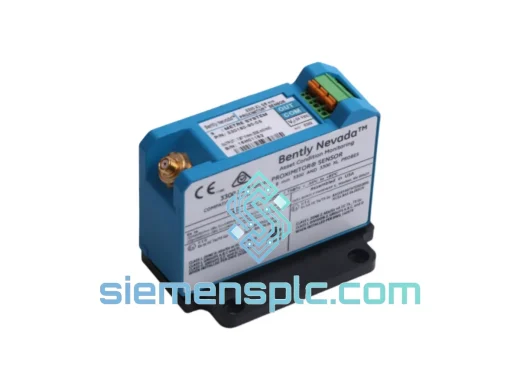
Bently Nevada 330101-32-70-05-12-05 Proximity Sensor
Request verified availability, condition, replacement risk review, packing options and courier lead time for 330101-32-70-05-12-05.
BrandBently Nevada
Part Number330101-32-70-05-12-05
ConditionAvailability Check
Lead TimeRFQ Confirmation
DocumentsDatasheet / photos by RFQ
ShippingExport packing available
Auto-filled RFQ
330101-32-70-05-12-05
Click Request Quote and the part number is inserted into the inquiry form automatically.
- Reply by email: [email protected]
- WhatsApp / Tel: +86 18359268345
- Mon-Sat 9:00-18:00 GMT+8
Procurement Data
Key Product Information
Core fields for model confirmation and RFQ routing. Detailed product narrative remains below.
- Brand
- Bently Nevada
- Primary Part Number
- 330101-32-70-05-12-05
- Product Type
- Proximity Transducer
- Series / Family
- 3301
- Country of Origin
- US
- Catalog Category
- Sensors & Switches
- Compliance
- API 670 (5th Ed.), IEC 60079, RoHS
Model confirmed for inquiry
330101-32-70-05-12-05
Send quantity, destination and urgency. The RFQ form keeps this part number attached.
Request Quote
Product Overview
330101-32-70-05-12-05 — Stop the Clock on Your Downtime. Ship Today from Xiamen.
Every hour a turbine or compressor sits idle costs real money — often $50,000 to $200,000 per hour in lost production, contractual penalties, and emergency labor. When your Bently Nevada 3300 XL proximity transducer fails, you don’t have time for a 12-week OEM lead time. We stock the 330101-32-70-05-12-05 and can have it on a DHL Express flight out of Xiamen within 24 hours of order confirmation. That’s the difference between a two-day outage and a two-week nightmare.
URGENT REQUIREMENT? Contact: [email protected] | WhatsApp: +86 18359268345
Quick Technical Datasheet
| Part Number | 330101-32-70-05-12-05 ✔ Ready to Ship |
| Brand / OEM | Bently Nevada (Baker Hughes) |
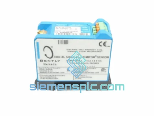
| Series | 3300 XL 8 mm Proximity Transducer System |
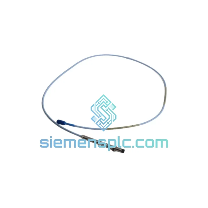
| Sensor Type | Eddy Current Non-Contact Proximity Probe |
| Probe Tip Diameter | 8 mm |
| Integral Cable Length | 3.2 m |
| Extension Cable Length | 7.0 m |
| Connector | 5-pin, 12 mm |
| Linear Range | 0.25 mm – 2.25 mm (10 – 90 mil) |
| Scale Factor | 7.87 V/mm (200 mV/mil) |
| Frequency Response | DC – 10,000 Hz (–3 dB) |
| Supply Voltage | –24 VDC nominal |
| Probe Temp Range | –35 °C to +177 °C |
| Driver Temp Range | –35 °C to +66 °C |
| Ingress Protection | IP67 |
| Target Material (std) | AISI 4140 Steel |
| Compliance | API 670 (5th Ed.), IEC 60079, RoHS |
| Country of Origin | USA |
| Stock Status | ✔ In Stock — Ships within 24 hrs |
Troubleshooting & Replacement Tips
After ten years of pulling failed proximity probes off turbine decks at 2 AM, here’s what actually matters when you’re doing a hot swap on the 330101-32-70-05-12-05:
Common Fault Signatures Before Full Failure
- OK LED flashing amber on the Proximitor driver (330180/330190): Gap voltage drifting outside –10 V to –18 V window. First suspect is probe tip contamination (oil coke, metallic debris) or a cracked integral cable near the probe body — flex the cable near the connector while watching the gap voltage on your DVM. If it jumps, the cable is the culprit, not the probe tip.
- Intermittent high-vibration trips with no process change: Check the extension cable connector at the junction box. The 5-pin 12 mm connector on this series is notorious for fretting corrosion in high-vibration environments. Clean with contact cleaner, re-torque to 1.5 N·m, and re-check gap voltage stability over 30 minutes before declaring the probe faulty.
- Constant –24 V output (rail low): Open circuit — probe integral cable severed, usually at the probe body exit point where the armored conduit terminates. Confirm with a continuity check: center pin to shield should read 7–9 Ω at room temperature for a healthy 3.2 m integral cable.
- Gap voltage reads –2 V to –4 V with probe installed: Probe tip is too far from the shaft — either the probe has backed out of its holder (check lock nut torque: 20 N·m minimum) or the shaft has dropped due to bearing wear. Verify shaft position with a dial indicator before condemning the probe.
Step-by-Step Replacement Procedure
- Step 1 — Isolate and document: Record the existing gap voltage (should be –10 V to –12 V at normal operating gap of 1.0 mm). This is your baseline for the new probe. Do not skip this — it saves 30 minutes of re-gapping time.
- Step 2 — De-energize the Proximitor driver: Remove the –24 VDC supply at the driver terminal block. Do not simply disconnect the probe cable with the driver powered — transient voltages can damage the driver input circuit.
- Step 3 — Remove the probe: Counter-rotate the probe body (left-hand thread on some holders — verify before applying force). If the probe is seized due to thermal cycling, apply penetrating oil at the thread interface and wait 15 minutes. Never use a pipe wrench on the probe body — you will crack the cable exit seal.
- Step 4 — Inspect the probe holder bore: Check for thread damage, debris, and concentricity. A damaged holder will misalign the new probe and produce a false eccentricity reading. Replace the holder if thread engagement is less than 5 full turns.
- Step 5 — Install the new 330101-32-70-05-12-05: Thread in by hand until snug, then back off ¼ turn. Connect the extension cable and re-energize the driver. Adjust gap until the driver output reads –10.0 V ± 0.2 V (1.0 mm gap). Lock the probe with the jam nut at 20 N·m.
- Step 6 — System verification: Confirm OK LED is solid green. Perform a slow-roll check at <200 RPM to verify runout is within API 670 limits (<25% of alarm setpoint). Log the new gap voltage in your maintenance record.
Configuration Notes
- The 330101-32-70-05-12-05 is a matched system component — it is factory-calibrated as a set with its extension cable and Proximitor driver. Mixing probe generations (e.g., pairing a 330101 probe with a legacy 3300/5 driver) requires re-verification of the scale factor. Refer to Bently Nevada TIL-073.
- No DIP switch or address configuration is required on the probe itself. All system addressing is handled at the monitor rack (3500 series) or the Proximitor driver enclosure.
- If replacing into a 3500/42M or 3500/45 monitor, verify the channel configuration in the rack software matches the 200 mV/mil scale factor. A mismatch will produce a calibration error alarm on startup.
Reliability in Harsh Conditions
The 330101-32-70-05-12-05 was not designed for a climate-controlled lab. It was designed for the bearing housing of a 40 MW gas turbine running at 3,000 RPM in a Malaysian offshore platform, a petrochemical compressor train in a Saudi desert, and a hydro turbine pit in a Norwegian fjord. Here’s what it handles without complaint:
- Thermal cycling: The probe body is constructed from 316 stainless steel with a PEEK-insulated tip assembly. It survives repeated thermal cycles from cold startup (–35 °C) to full-load bearing housing temperatures (+177 °C) without dimensional drift that would shift the gap calibration.
- Vibration and shock: The integral cable uses a multi-strand, individually shielded construction that resists fatigue fracture at the probe body exit — the highest-stress point in the cable run. Tested to IEC 60068-2-6 (sinusoidal vibration) and IEC 60068-2-27 (mechanical shock).
- Moisture and contamination: IP67 rating means the probe survives temporary immersion to 1 m depth. In practice, this covers steam condensate flooding in turbine enclosures and high-pressure wash-down during maintenance outages. The 5-pin connector uses a captive O-ring seal — inspect and replace the O-ring at every probe change.
- Chemical exposure: The cable jacket is rated for continuous exposure to lubricating oils, hydraulic fluids, and mild cleaning solvents. Avoid prolonged contact with aromatic hydrocarbons (toluene, xylene) which will degrade the jacket over time.
- EMI/RFI immunity: The coaxial cable construction with continuous shield coverage provides >60 dB rejection of common-mode interference — critical in environments with large VFDs, welding equipment, or high-voltage switchgear nearby.
Global Express Logistics
Our warehouse is located in Xiamen, Fujian Province — one of China’s primary export hubs with direct access to DHL, FedEx, and UPS international gateways. Here’s how a typical urgent order moves:
- Order confirmed before 14:00 CST: Same-day pick, pack, and handover to DHL Express or FedEx International Priority.
- Transit times (typical): Southeast Asia 1–2 days | Middle East 2–3 days | Europe 3–4 days | North America 3–5 days | Australia 3–4 days.
- Export documentation: Commercial invoice, packing list, and Certificate of Origin are prepared same day. For orders requiring ATEX documentation or third-party inspection (SGS, Bureau Veritas), allow one additional business day.
- Customs clearance: We declare all shipments accurately under HS Code 9031.80 (instruments for measuring or checking). DDP (Delivered Duty Paid) terms available for most destinations — you receive the part, we handle the import duties.
- Tracking: AWB number sent via email and WhatsApp within 2 hours of carrier pickup. Real-time tracking link included.
- Emergency freight: For critical plant shutdowns, we can arrange hand-carry courier service to most major industrial hubs. Contact us directly to discuss options.
Contact Information
Email: [email protected] | WhatsApp: +86 18359268345 | Web: siemensplc.com
© 2026 siemensplc.com. All rights reserved.
Ready to quote
[email protected]
Send This Part Number to Sales
RFQ workflow
Quality workflow ->
Confirmation Process
01Model confirmation
We check the full part number, brand, series and visible nameplate information before quotation.
02Availability reply
Sales confirms stock path, condition option, quantity and realistic lead time for export dispatch.
03Packing & courier
DHL, FedEx, UPS or buyer courier arrangements can be reviewed with packing requirements.
Continue sourcing
Browse full catalog ->
Related Automation Parts
Similar brand or category products for fast comparison and multi-item RFQ lists.
Bently Nevada
RFQ Ready
Bently Nevada 330180-52-05 Proximity Transducer
3301
Origin US
Proximity Transducer
Bently Nevada
RFQ Ready
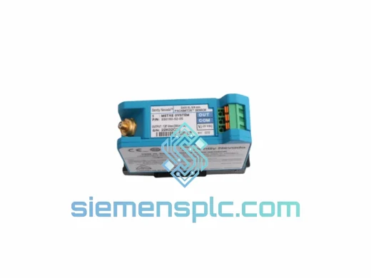
Bently Nevada 330180-51-05 Proximitor Sensor
3301
Origin US
Vibration Sensor
Bently Nevada
RFQ Ready
Bently Nevada 330180-51-00 Proximitor Sensor
3301
Origin US
Vibration Monitoring Sensor