Bently Nevada
RFQ Ready
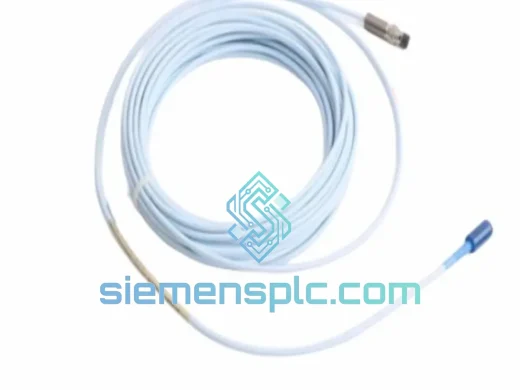
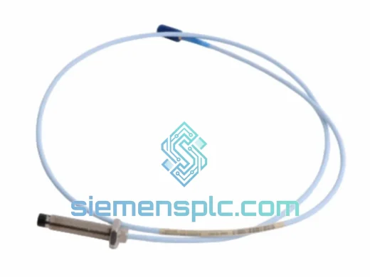
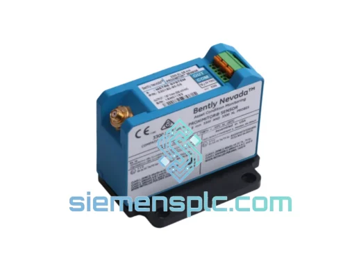
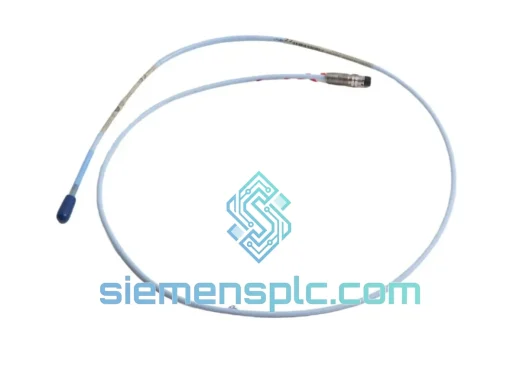
Bently Nevada 330196-05-30-10-00 Proximity Probe – 3300 XL ETR
3301
Origin US
Proximity Probe
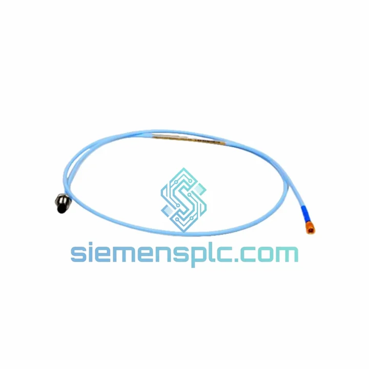
Request verified availability, condition, replacement risk review, packing options and courier lead time for 330104-02-12-10-01-00.
Click Request Quote and the part number is inserted into the inquiry form automatically.
Core fields for model confirmation and RFQ routing. Detailed product narrative remains below.
A failed proximity transducer in a 3300 XL loop doesn’t just trigger an alarm — it takes your entire vibration channel offline. On a critical turbine or compressor train, that means a forced shutdown, a bypassed protection channel, or a compliance violation under API 670. None of those options are acceptable. The Bently Nevada 330104-02-12-10-01-00 is a 5 mm eddy-current proximity transducer system matched to the 3300 XL driver/extension cable architecture. We carry verified stock in Xiamen and cut the same-day shipping deadline at 15:00 CST. If you’re reading this during a turnaround, stop reading and contact us now.
URGENT REQUIREMENT? Contact: [email protected] | WhatsApp: +86 18359268345
| Parameter | Specification |
|---|---|
| Part Number | 330104-02-12-10-01-00 |
| Manufacturer | Bently Nevada (Baker Hughes) |
| Product Series | 3300 XL Proximity Transducer System |
| Sensing Technology | Eddy-Current, Non-Contact |
| Probe Tip Diameter | 5 mm |
| Thread | 10-32 UNF |
| Integral Cable Length | 2 m |
| Extension Cable | 12 m (330130 Series matched) |
| Linear Measurement Range | 2.0 mm (80 mil) |
| Scale Factor | 7.87 V/mm (200 mV/mil) |
| Frequency Response | DC to 10,000 Hz |
| Supply Voltage | -24 VDC nominal |
| Output Voltage Range | -2 VDC to -18 VDC |
| Probe Operating Temp | -35 °C to +177 °C |
| Driver Operating Temp | -35 °C to +85 °C |
| Standard Target Material | AISI 4140 Steel |
| Certifications | API 670, CE Marked |
| Compatible Racks | Bently Nevada 3300 / 3500 Series |
| Stock Status | ✔ In Stock — Ready to Ship from Xiamen |
Ten years of field work on rotating machinery teaches you one thing fast: most 3300 XL failures are misdiagnosed. Before you condemn the probe, work through this sequence.
Step 1 — Confirm the fault is in the transducer system, not the monitor card. Disconnect the driver output at the monitor rack terminal block and connect a calibrated DC voltage source set to -10.5 VDC. If the monitor channel clears its Not-OK alarm, the fault is upstream of the rack — in the driver, extension cable, or probe. If the alarm persists with a known-good voltage source, the monitor card itself is suspect. Don’t swap the transducer until you’ve ruled out the rack.
Step 2 — Measure driver output voltage at the field junction box. With the probe installed at its nominal gap, the 330104-02-12-10-01-00 driver should output -10.5 VDC ± 0.5 V on AISI 4140 steel. A reading outside -10.0 to -11.0 VDC at nominal gap means either the gap has shifted, the target surface has changed (corrosion, scoring, chrome plating), or the driver oscillator is degrading. Measure first, replace second.
Step 3 — Gap setting on the replacement probe. The 10-32 UNF thread has a pitch of 0.794 mm per turn. From tip contact, back the probe out 1.25 turns to achieve approximately 1.0 mm gap as a starting point. Fine-adjust while monitoring driver output voltage until you read -10.5 VDC. Lock the jam nut at 2.0–2.5 N·m — no more. The 5 mm probe body is ceramic-tipped; over-torquing the jam nut against the bracket will crack the tip insert. Verify gap voltage again after locking.
Step 4 — Extension cable integrity. The 330130 armored extension cable is a matched component — it is not interchangeable with cables from other Bently Nevada series without recalibration. Flex fatigue at the probe-end connector is the most common cable failure mode and is invisible externally. Disconnect both ends and measure center-conductor-to-shield resistance. On a 12 m run, anything above 1.5 Ω indicates a compromised conductor. Measure shield continuity separately. A broken shield on a proximity cable introduces 50/60 Hz noise directly into the vibration signal — you’ll see it as a fixed-frequency spike on the spectrum that doesn’t track shaft speed.
Step 5 — Driver supply voltage check. The 330104 driver requires a stable -24 VDC supply. Measure at the driver terminal block under load, not at the panel supply output. Cable resistance in long field runs can drop the supply below the -21 VDC minimum threshold, causing the driver to lose oscillation and assert a Not-OK condition. If you’re seeing intermittent Not-OK alarms that clear on power cycling, check the supply rail first.
Common configuration note: This transducer system does not have DIP switches or firmware — it is a passive analog system. There is no address configuration required. The only setup parameter is the physical gap, set mechanically and verified electrically. If you are replacing a probe in a 3500 rack with a Keyphasor or thrust position channel, confirm the channel configuration in the rack software matches the 200 mV/mil scale factor of the 330104 system before returning the channel to service.
The 330104-02-12-10-01-00 probe body is machined from 316L stainless steel with a PEEK ceramic composite tip insert. That material combination was chosen specifically for bearing housing environments: resistance to turbine oil, process gas condensate, amine-based cleaning solvents, and the thermal cycling that comes with repeated startups and shutdowns. The probe does not have any moving parts, seals, or wear surfaces — the eddy-current measurement principle is inherently immune to mechanical fatigue.
The armored extension cable uses a stainless steel braid over a PTFE-insulated coaxial core. PTFE insulation does not absorb moisture, does not crack under repeated thermal cycling, and maintains its dielectric properties across the full operating temperature range. The stainless braid provides both EMI shielding and mechanical protection against conduit abrasion. In installations where the cable must pass through areas with high radiated EMI — near large VFDs, transformer rooms, or MCC switchgear — the braid continuity is critical. Verify it at installation and at every planned maintenance interval.
Vibration immunity is a function of the measurement physics. Because the probe tip never contacts the target shaft, there is no mechanical coupling path for vibration to corrupt the measurement. The system has been validated to 20 g broadband vibration from 10 to 2,000 Hz. In practice, the limiting factor in high-vibration installations is the mechanical integrity of the probe mounting bracket and the cable routing — loose cable runs that allow the armored cable to vibrate against structure will eventually fatigue the cable at the connector, not the probe itself. Secure cable runs with stainless steel clamps at intervals no greater than 300 mm in high-vibration zones.
Our Xiamen warehouse operates on a same-day dispatch cut-off of 15:00 CST for confirmed in-stock orders. The process from your purchase order to carrier handoff runs as follows:
We have shipped industrial instrumentation to over 40 countries. If your destination has import licensing requirements or specific customs documentation needs for industrial sensors, contact us before placing the order — we will advise on the exact documentation package required for your port of entry.
Technical questions before you order? Need a lead time confirmation for your maintenance planner? Contact us directly.
📧 Email: [email protected]
💬 WhatsApp: +86 18359268345
🌐 Web: siemensplc.com
© 2026 siemensplc.com. All rights reserved.
We check the full part number, brand, series and visible nameplate information before quotation.
Sales confirms stock path, condition option, quantity and realistic lead time for export dispatch.
DHL, FedEx, UPS or buyer courier arrangements can be reviewed with packing requirements.
Similar brand or category products for fast comparison and multi-item RFQ lists.