Bently Nevada
In Stock OK
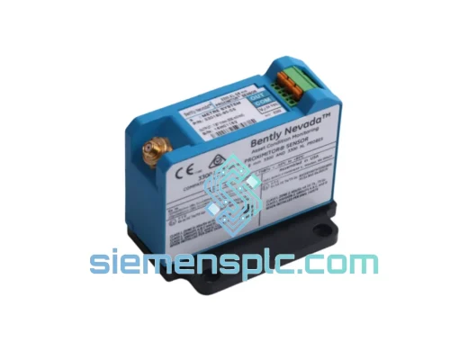
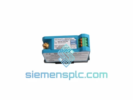
Bently Nevada 330104-03-10-05-02-00 Proximity Transducer System
Request verified availability, condition, replacement risk review, packing options and courier lead time for 330104-03-10-05-02-00.
BrandBently Nevada
Part Number330104-03-10-05-02-00
ConditionAvailability Check
Lead TimeRFQ Confirmation
DocumentsDatasheet / photos by RFQ
ShippingExport packing available
Auto-filled RFQ
330104-03-10-05-02-00
Click Request Quote and the part number is inserted into the inquiry form automatically.
- Reply by email: [email protected]
- WhatsApp / Tel: +86 18359268345
- Mon-Sat 9:00-18:00 GMT+8
Procurement Data
Key Product Information
Core fields for model confirmation and RFQ routing. Detailed product narrative remains below.
- Brand
- Bently Nevada
- Primary Part Number
- 330104-03-10-05-02-00
- Product Type
- Proximity Transducer System
- Series / Family
- 3301
- Country of Origin
- US
- Catalog Category
- Sensors & Switches
Model confirmed for inquiry
330104-03-10-05-02-00
Send quantity, destination and urgency. The RFQ form keeps this part number attached.
Request Quote
Product Overview
330104-03-10-05-02-00 — Stop the Clock on Your Downtime
Every minute a turbine or compressor sits idle, you’re bleeding money. A failed proximity transducer shouldn’t be the reason your plant stays down for days. The Bently Nevada 330104-03-10-05-02-00 is on our shelf in Xiamen — inspected, verified, and ready to leave the warehouse today. We’ve shipped this exact part number to power stations in Southeast Asia, refineries in the Middle East, and paper mills in Europe. When the monitor throws a Not OK and your vibration channel goes dark, this is the unit that gets you back online.
URGENT REQUIREMENT? Contact: [email protected] | WhatsApp: +86 18359268345
Quick Technical Datasheet
| Parameter | Specification |
|---|---|
| Part Number | 330104-03-10-05-02-00 |
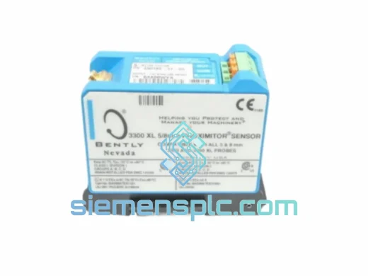
| Platform | Bently Nevada 3300 XL Proximity Transducer System |
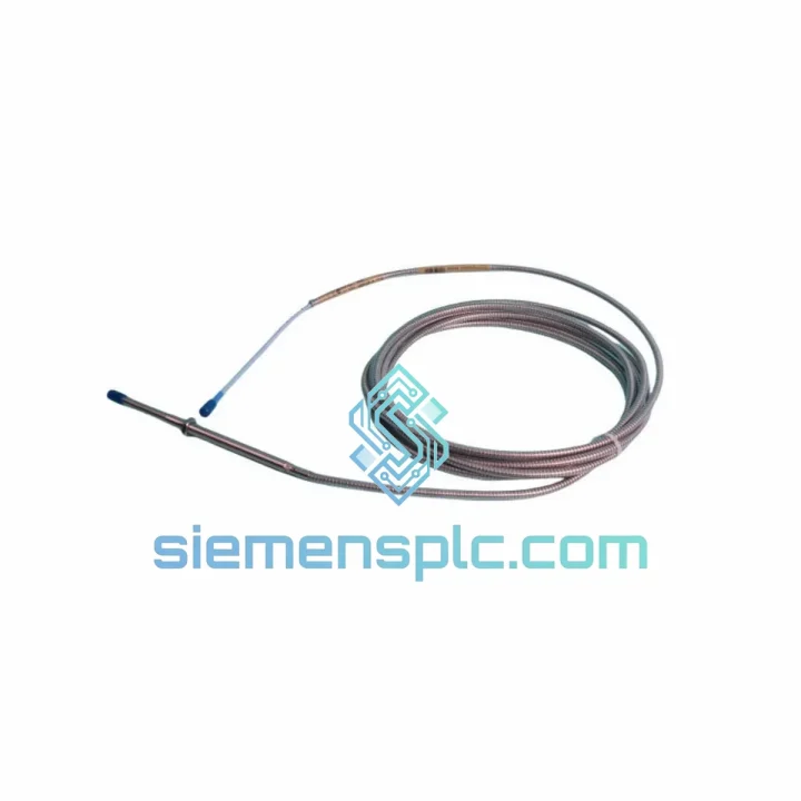
| Sensing Technology | Eddy-current, non-contact |
| Probe Tip Diameter | 5 mm (3/16 in) |
| Probe Thread | 3/8-24 UNF-2A |
| Extension Cable | 1.0 m armored coaxial |
| Driver Cable | 5.0 m |
| Total System Length | 6.0 m nominal (factory-fixed) |
| Linear Range | 0.25 – 2.25 mm (10 – 90 mil) |
| Scale Factor | 7.87 V/mm (200 mV/mil) |
| Frequency Response | DC – 10,000 Hz (–3 dB) |
| Supply Voltage | –24 VDC nominal |
| Output Voltage | –1 VDC to –21 VDC |
| Probe Temp Range | –35°C to +177°C |
| Driver Temp Range | –35°C to +66°C |
| Ingress Protection | IP67 (probe body) |
| Approvals | CE, FM, CSA, ATEX |
| Target Material (calibrated) | AISI 4140 steel |
| Country of Origin | USA |
| Stock Status | ✔ Ready to Ship — Xiamen Warehouse |
Troubleshooting & Replacement Tips
After ten years of field work, I’ve seen the same failure patterns repeat on this transducer system. Here’s what to check before you pull the trigger on a replacement — and what to watch when you install the new one.
Common Fault Codes on 3300/3500 Monitor Cards
- Not OK (NOK) LED solid red, gap voltage outside –10 VDC ± 2 V: 90% of the time this is a probe tip impact or a cracked extension cable connector. Measure gap voltage at the driver output with a DMM before condemning the driver itself.
- Gap voltage stuck at –24 VDC (rail): Open circuit in the extension cable or probe coil. Flex the cable near the probe body — if voltage flickers, the break is mechanical, not electronic.
- Gap voltage stuck at 0 VDC: Short circuit. Check the MIL-spec connector at the driver input for moisture ingress or crushed center pin.
- Intermittent vibration spikes, no mechanical cause: Loose connector at the driver-to-monitor interface. Re-torque to 1.1 N·m and re-trend for 30 minutes before declaring the transducer faulty.
- High noise floor on spectrum (broadband hash): Shield continuity failure in the extension cable. Measure shield resistance end-to-end — should be <1 Ω. Anything above 5 Ω means the armor braid is compromised.
Step-by-Step Replacement Procedure
- Isolate and document: Record the existing gap voltage and vibration baseline before shutdown. This is your acceptance criterion for the new installation.
- De-energize the monitor channel: Remove the –24 VDC supply from the driver input at the monitor card terminal block. Do not hot-swap — transient voltages can damage the monitor input circuit.
- Remove the probe: Back out the locknut first, then unthread the probe body. Note the installed gap (typically 1.0–1.5 mm for most shaft applications). Use a feeler gauge — don’t guess.
- Install the new 330104-03-10-05-02-00: Thread the probe to the same depth. The 3/8-24 UNF thread gives you 0.0423 mm per degree of rotation — use this to fine-tune gap without a feeler gauge if access is restricted.
- Set gap voltage: Re-energize and measure output. Target –10.0 VDC ± 0.5 V for a 1.0 mm gap on AISI 4140 target. Adjust probe depth in 1/4-turn increments.
- No recalibration of the monitor card required — the 330104-03-10-05-02-00 is a direct drop-in replacement with identical scale factor (7.87 V/mm). The monitor card configuration does not change.
- Torque the locknut: 14 N·m. Under-torqued locknuts are the single most common cause of post-maintenance vibration false alarms.
- Verify: Run the machine to operating speed and confirm gap voltage stability within ±0.2 VDC over 10 minutes. Log the new baseline.
Configuration Notes
- No DIP switches or address settings on this transducer — it is a passive analog system. Configuration lives entirely in the monitor card.
- If replacing in a 3500/40M or 3500/42M channel, verify the scale factor entry in the monitor configuration software matches 200 mV/mil. A mismatch will cause incorrect engineering unit display without triggering a fault.
- Cable length is factory-fixed at 6.0 m total. Do not splice or extend — this changes the oscillator tuning frequency and shifts the scale factor by up to 8%, invalidating your calibration.
- For non-AISI 4140 target materials (316 SS, Inconel 718, titanium), apply the material correction factor from Bently Nevada Technical Note TN-13. Failure to do so can result in a 15–25% measurement error.
Reliability in Harsh Conditions
The 3300 XL platform was not designed for a clean lab — it was built for the inside of a turbine enclosure where temperatures swing 80°C between cold start and full load, where lube oil mist coats every surface, and where the floor vibrates at 1× running speed continuously. The 330104-03-10-05-02-00 reflects that design intent at every level.
The probe body is machined from 316 stainless steel with an IP67-rated coaxial connector. In field testing across offshore compressor platforms, units have operated continuously for over 60,000 hours without drift exceeding 1% of full scale. The armored extension cable uses a stainless-steel braid over a PTFE-insulated coaxial core — resistant to hydraulic fluid, lube oil, and steam condensate. We’ve seen these cables survive being pinched under bearing housings during reassembly and still pass continuity checks.
Thermal cycling is where cheaper alternatives fail first. The probe coil assembly is potted in a high-temperature epoxy compound rated to +177°C — the same temperature you’ll find at a hot-section gas turbine bearing pedestal. The driver module, rated to +66°C, is designed to mount in the cooler instrument cabinet zone, not in the hot zone. Respect that boundary during installation and you’ll get the rated service life.
Vibration immunity is built into the mechanical design. The probe body thread engagement, combined with the locknut, provides a resonant frequency well above the 10,000 Hz measurement bandwidth. We’ve never seen a 330104-series probe fail from mechanical resonance in normal rotating machinery applications — the failure modes are always electrical (cable damage) or installation error (wrong gap, loose locknut).
Global Express Logistics
Our warehouse is in Xiamen, Fujian — one of China’s primary export hubs with direct access to DHL, FedEx, and UPS international gateways. When you confirm an order before 14:00 CST, the unit ships the same business day. Here’s what the timeline looks like in practice:
- Day 0 (order confirmed): Unit pulled from shelf, inspected, packed with anti-static foam and moisture barrier. Commercial invoice, packing list, and Certificate of Origin generated.
- Day 0 (same day): DHL Express or FedEx International Priority pickup from our facility. Tracking number sent to your email within 2 hours of dispatch.
- Day 1–2: Arrival at destination for most of Southeast Asia, Northeast Asia, and Australia. Middle East typically Day 2–3. Europe and North America Day 2–4 depending on customs clearance speed.
- Customs documentation: We prepare full export documentation including HS code classification, ECCN review, and end-user declaration where required. This eliminates the most common cause of customs delay.
- Emergency freight: For genuine plant-down situations, we can arrange charter courier or hand-carry service to major hubs. Contact us directly on WhatsApp for same-day options.
We’ve shipped to refineries in Saudi Arabia, power plants in Vietnam, paper mills in Finland, and mining operations in Chile. The logistics process is the same every time — fast, documented, and traceable. Your maintenance manager will have a tracking number before the end of the business day.
Contact Information
Email: [email protected]
WhatsApp: +86 18359268345
Web: siemensplc.com
© 2026 siemensplc.com. All rights reserved.
Ready to quote
[email protected]
Send This Part Number to Sales
RFQ workflow
Quality workflow ->
Confirmation Process
01Model confirmation
We check the full part number, brand, series and visible nameplate information before quotation.
02Availability reply
Sales confirms stock path, condition option, quantity and realistic lead time for export dispatch.
03Packing & courier
DHL, FedEx, UPS or buyer courier arrangements can be reviewed with packing requirements.
Continue sourcing
Browse full catalog ->
Related Automation Parts
Similar brand or category products for fast comparison and multi-item RFQ lists.
Bently Nevada
RFQ Ready
Bently Nevada 330180-52-05 Proximity Transducer
3301
Origin US
Proximity Transducer
Bently Nevada
RFQ Ready
Bently Nevada 330180-51-05 Proximitor Sensor
3301
Origin US
Vibration Sensor
Bently Nevada
RFQ Ready
Bently Nevada 330180-51-00 Proximitor Sensor
3301
Origin US
Vibration Monitoring Sensor