Bently Nevada
RFQ Ready
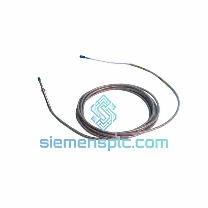
Bently Nevada 330196-05-30-10-00 Proximity Probe – 3300 XL ETR
3301
Origin US
Proximity Probe
Request verified availability, condition, replacement risk review, packing options and courier lead time for 330104-18-22-10-02-00.
Click Request Quote and the part number is inserted into the inquiry form automatically.
Core fields for model confirmation and RFQ routing. Detailed product narrative remains below.
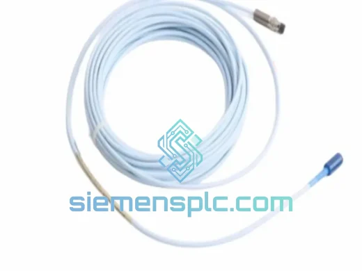
The 330104-18-22-10-02-00 is a complete three-component eddy current proximity transducer assembly manufactured by Bently Nevada, operating within the 3300 XL platform. Its primary function is continuous, non-contact measurement of radial shaft displacement and vibration in rotating machinery — turbines, compressors, pumps, and gearboxes — where contact-based sensing is mechanically impractical and signal latency is operationally unacceptable.
This assembly is configured as follows: 18 mm probe diameter, 22-inch (558.8 mm) integral armored cable, 10-meter coaxial extension cable, standard 200 mV/mil (7.87 V/mm) sensitivity, and a nominal –24 VDC bias output. The configuration code 02-00 designates standard connector termination and non-intrinsically-safe driver pairing, making it the default selection for general-purpose industrial installations not requiring ATEX Zone 0 compliance.
In a machinery protection control loop, this transducer occupies the front-end sensing position. Its analog DC output feeds directly into Bently Nevada 3300 series monitor cards — such as the 3300/16 Dual Vibration Monitor or the 3300/25 Keyphasor Module — where the signal is conditioned, compared against alarm and danger setpoints, and used to drive relay outputs for automatic machine shutdown. The transducer’s DC-to-10,000 Hz frequency response ensures that both quasi-static shaft position drift (thermal bow, bearing wear) and high-frequency vibration events (blade passing frequency, subsynchronous instability) are captured within a single measurement channel without signal aliasing.
Real-time Stock & RFQ: [email protected] | WhatsApp: +86 18359268345
| Parameter | Value |
|---|---|
| Part Number / SKU | 330104-18-22-10-02-00 |
| Platform / Series | Bently Nevada 3300 XL Proximity Transducer System |
| Probe Diameter | 18 mm |
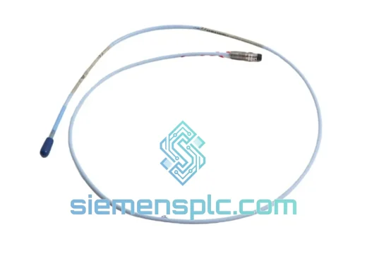
| Integral Cable Length | 22 inches (558.8 mm), armored construction |
| Extension Cable Length | 10 meters, coaxial, low-loss dielectric |
| Sensitivity | 200 mV/mil ± 10% (7.87 V/mm) |
| Bias Voltage Output | –24 VDC nominal (–18 to –26 VDC operating range) |
| Linear Measurement Range | 25–325 mil (0.635–8.255 mm gap) |
| Frequency Response (–3 dB) | DC to 10,000 Hz |
| Supply Voltage | –24 VDC ± 1 VDC |
| Supply Current | ≤ 12 mA (driver + probe) |
| Operating Temperature — Probe | –35°C to +121°C |
| Operating Temperature — Driver | –35°C to +66°C |
| Standard Target Material | AISI 4140 steel (other alloys require calibration correction) |
| Output Impedance | 100 Ω (driver output) |
| Connector Type | Standard per configuration code 02-00 |
| Compliance Standard | API 670 5th Edition; CE; FM; CSA |
| Approximate Assembly Weight | 210 g |
| Country of Origin | United States |
| Warranty | 12 months against manufacturing defects |
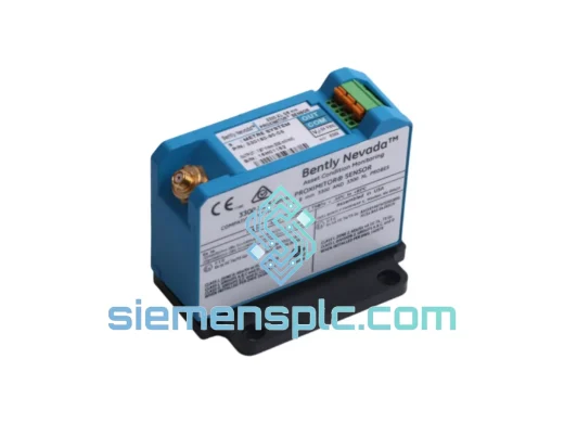
The 330104-18-22-10-02-00 operates on the principle of electromagnetic impedance modulation. The probe tip houses a flat coil wound on a ferrite core, driven by the oscillator stage of the paired driver/oscillator-demodulator at a carrier frequency of approximately 1.0 MHz. When the probe tip is positioned within its linear range of a conductive target, eddy currents are induced on the target surface. These eddy currents create a counter-magnetic field that loads the probe coil, reducing its effective inductance and increasing resistive losses — a measurable change in coil impedance proportional to the air gap distance.
The driver’s demodulator stage extracts this impedance variation from the carrier signal and converts it to a DC voltage output. The transfer function is linear within the 25–325 mil gap range, with a slope of exactly 200 mV/mil. The –24 VDC bias at mid-gap (approximately 175 mil) allows the monitor card to detect both positive and negative gap excursions — shaft moving toward or away from the probe — without signal clipping.
EMC Design: The coaxial extension cable uses a double-shielded construction with a low-capacitance dielectric. The outer shield is grounded at the driver end only (single-point grounding), preventing ground loop currents from injecting common-mode noise into the signal path. This architecture maintains signal integrity in environments with high-frequency switching noise from variable-frequency drives (VFDs) operating at 2–16 kHz carrier frequencies — a common interference source in compressor and pump stations.
Thermal Stability: The probe coil assembly uses a temperature-compensated ferrite core material. Over the –35°C to +121°C probe operating range, sensitivity drift is maintained within ±1% of nominal — a critical specification for steam turbine applications where probe body temperatures can approach 100°C during normal operation. The integral cable’s armored jacket provides mechanical protection against abrasion and vibration fatigue at the probe-to-cable junction, which is the highest-stress point in the assembly.
Calibration Traceability: Each 330104 assembly is factory-calibrated as a matched system — probe, integral cable, and extension cable are characterized together. The calibration data is encoded in the driver’s trim resistor network. Substituting any individual component without recalibration introduces a systematic sensitivity error that cannot be corrected at the monitor card level, which is why field cable length modification is not supported.
Every 330104-18-22-10-02-00 unit supplied through siemensplc.com is sourced as genuine Bently Nevada original equipment — not aftermarket, not cloned, and not rebranded. Units are procured through authorized industrial distribution channels and verified OEM surplus programs. Prior to dispatch, each assembly undergoes a structured pre-shipment inspection protocol: visual examination of probe tip, coil housing, and connector terminations; continuity and insulation resistance check on the extension cable; and documentation verification confirming part number, date code, and configuration code against the physical label.
Shipments originate from our warehouse in Xiamen, China — a major international logistics hub with direct access to DHL Express, FedEx International Priority, and UPS Worldwide Expedited services. Standard transit times are 3–5 business days to Europe and North America, 2–3 business days to Southeast Asia and the Middle East. All shipments are packed to IEC 60068-2 transport vibration and shock standards: probe assemblies are individually foam-cushioned, extension cables are coiled to a minimum bend radius of 10× cable diameter, and the complete assembly is sealed in an anti-static bag before boxing. Export documentation — commercial invoice, packing list, and HS code 9031.80 classification — is prepared for customs clearance in all major import jurisdictions.
A 12-month warranty against manufacturing defects is provided on all units. Warranty claims are processed within 5 business days of receipt of the returned unit. Technical support — including gap setting guidance, cable routing recommendations, and monitor card compatibility verification — is available directly from our engineering team via email and WhatsApp at no additional charge.
Email: [email protected]
WhatsApp: +86 18359268345
Web: siemensplc.com
Location: Xiamen, China
© 2026 siemensplc.com. All rights reserved.
We check the full part number, brand, series and visible nameplate information before quotation.
Sales confirms stock path, condition option, quantity and realistic lead time for export dispatch.
DHL, FedEx, UPS or buyer courier arrangements can be reviewed with packing requirements.
Similar brand or category products for fast comparison and multi-item RFQ lists.