Bently Nevada
RFQ Ready
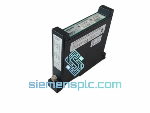
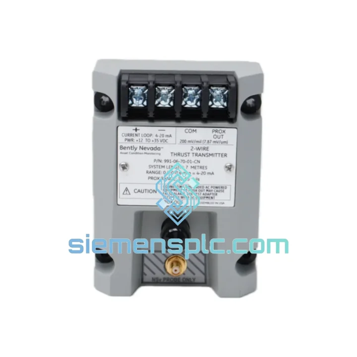
Bently Nevada 991-06-XX-01-00 Thrust Position Transmitter
3500 Series
Origin US
Thrust Position Transmitter
Request verified availability, condition, replacement risk review, packing options and courier lead time for 991-06-70-02-00.
Click Request Quote and the part number is inserted into the inquiry form automatically.
Core fields for model confirmation and RFQ routing. Detailed product narrative remains below.
In high-speed rotating machinery — gas turbines, centrifugal compressors, steam turbines, and large pump trains — axial thrust bearing condition is a primary determinant of machine availability. Thrust bearing failure does not follow a gradual degradation curve visible to periodic inspection; it accelerates. A rotor that has migrated 0.3 mm beyond its normal axial float zone may be within minutes of contact between rotating and stationary components. The Bently Nevada 991-06-70-02-00 is the signal conditioning transmitter that converts the raw gap-voltage output of an eddy-current proximity probe measurement chain into a calibrated, loop-compatible 4–20 mA signal, delivering a continuous, real-time representation of rotor axial position to the 3500 Series rack monitor with the accuracy and response speed that API 670 protection logic demands.
The 991-06-70-02-00 occupies a specific and non-substitutable position in the Bently Nevada measurement architecture. The eddy-current proximity probe generates a gap-dependent voltage at the Proximitor driver output — typically in the –2 VDC to –18 VDC range for 3300 XL and 7200 Series drivers operating on a –24 VDC bias supply. This voltage is a precise analog of probe-to-target gap, but it is not directly compatible with the 4–20 mA analog input cards of the 3500 rack or the plant DCS. The 991-06-70-02-00 performs the span linearization, voltage-to-current conversion, and galvanic isolation required to bridge these two domains without introducing measurement error or ground loop interference into the protection loop.
The transmitter accepts the Proximitor gap voltage at a high-impedance differential input stage, which presents a load of less than 10 kΩ to the Proximitor output — well within the drive capability of the 3300 XL and 7200 Series drivers and low enough to avoid perturbing the oscillator bias circuit that governs probe sensitivity. An internal span-adjustment network maps the configured gap-voltage window to the 4–20 mA output range. The mapping is linear across the full measurement span, with temperature-compensated resistor networks maintaining span accuracy to within ±0.5% of full scale across the –40°C to +85°C operating temperature range. This level of thermal stability is not achievable with general-purpose signal conditioners whose internal references drift at rates that accumulate to several percent of span over a seasonal temperature cycle in an outdoor installation.
Galvanic isolation between the probe circuit and the output current loop is a functional requirement, not an optional feature, in large rotating machinery installations. Ground potential differences of 5 V to 20 V between machine frame ground and control room instrument ground are routine in facilities where high-current motor drives, transformer neutrals, and grounding electrode systems share a common ground grid. Without isolation, these potentials appear as DC offset errors on the gap-voltage signal. A 10 V ground potential difference on a measurement chain with a sensitivity of 7.87 mV/µm (200 mV/mil) produces a false axial displacement reading of approximately 1.27 mm — sufficient to mask real thrust bearing wear or generate a spurious trip on a machine that is operating normally. The 991-06-70-02-00 eliminates this error source by breaking the galvanic path between the probe circuit ground and the instrument loop ground, maintaining measurement integrity regardless of site grounding topology.
The fault detection circuit operates continuously and independently of the output conversion path. It monitors the input gap voltage against configurable under-range and over-range thresholds corresponding to probe cable open-circuit, Proximitor power loss, and probe pullout conditions. When the input falls outside the valid measurement window, a hardware comparator drives the output to a configurable upscale state (greater than 20.5 mA) or downscale state (less than 3.6 mA) within 100 ms. This response time is deterministic — it is set by the comparator propagation delay and output slew rate, not by a software polling cycle — and it meets the not-OK detection response time requirements of API 670 (5th Edition), Section 5.3. The 3500 rack monitor’s not-OK relay responds to the fault-state output within its own configured response time, initiating a protective action before the DCS operator has acknowledged the alarm.
The enclosure is DIN-rail compatible and rated IP20, suitable for installation in control room marshalling panels, field junction boxes, and equipment skid enclosures. The 18–30 VDC supply voltage range accommodates both 24 VDC instrument loops and 28 VDC rack-supplied circuits without derating, and the unit draws less than 25 mA from the supply rail exclusive of the loop output current. EMC performance meets the IEC 61000-4 series test suite — including ESD (Level 3), radiated immunity (Level 3), electrical fast transient (Level 3), surge (Level 2), and conducted RF immunity (Level 3) — through a combination of differential input topology with common-mode rejection ratio exceeding 60 dB at 50/60 Hz, supply rail filtering, and a shielded enclosure that attenuates radiated fields from adjacent VFD power cables and high-current bus bars.
For procurement engineers managing 3500 Series installed base, the 991-06-70-02-00 is a direct form-fit-function replacement for earlier Bently Nevada axial transmitter variants within the 3500 platform. All units supplied by siemensplc.com are sourced through verified industrial channels, inspected against Bently Nevada original part-marking standards, and shipped with full documentation from Xiamen, China to destinations worldwide.
Real-time Stock & RFQ: [email protected] | WhatsApp: +86 18359268345
| Parameter | Specification |
|---|---|
| Part Number | 991-06-70-02-00 |
| Manufacturer | Bently Nevada (Baker Hughes) |
| Platform Compatibility | 3500 Series Machinery Protection System |
| Functional Role | Axial Thrust Position Signal Conditioner / Transmitter |
| Input Voltage Range | –2 VDC to –18 VDC (Proximitor gap voltage) |
| Compatible Proximitor Drivers | 3300 XL 8 mm, 3300 XL 5 mm, 7200 Series (–24 VDC bias) |
| Output Signal | 4–20 mA, two-wire, loop-powered |
| Output Loop Compliance | ≥ 600 Ω at 20 mA |
| Fault Output — Upscale | > 20.5 mA (configurable) |
| Fault Output — Downscale | < 3.6 mA (configurable) |
| Fault Detection Response Time | ≤ 100 ms (hardware comparator, deterministic) |
| Span Accuracy | ±0.5% of full scale across operating temperature range |
| Measurement Span | Configurable; typical ±0.5 mm to ±2.0 mm full scale |
| Input Impedance | < 10 kΩ differential |
| Common-Mode Rejection Ratio | > 60 dB at 50/60 Hz |
| Galvanic Isolation | Probe circuit to output loop (transformer or optocoupler topology) |
| Supply Voltage | 18–30 VDC |
| Supply Current | ≤ 25 mA (excluding loop output) |
| Operating Temperature | –40°C to +85°C |
| Storage Temperature | –50°C to +100°C |
| Enclosure Rating | IP20, DIN-rail mount |
| EMC Standards | IEC 61000-4-2 (ESD L3), -4-3 (RF L3), -4-4 (EFT L3), -4-5 (Surge L2), -4-6 (Conducted L3) |
| Regulatory Approvals | CE marked; SIL-capable within 3500 system SIL documentation |
| Compatible Rack Monitors | 3500/42M Position Monitor, 3500/44M Thrust & Differential Expansion Monitor, 3500/45 |
| Country of Origin | USA |
| Approximate Weight | 500 g |
| Warranty | 12 months from date of shipment |
The internal signal path of the 991-06-70-02-00 is structured as three discrete functional stages, each with a defined role in the measurement chain.
Stage 1 — Differential Input Receiver: The input stage presents a high-impedance differential load to the Proximitor output. The differential topology rejects common-mode voltages — including ground potential differences and inductively coupled noise from adjacent power cables — before they reach the conversion circuitry. The input stage does not load the Proximitor’s internal –24 VDC bias oscillator, preserving the probe gap-voltage linearity that the Proximitor’s calibration depends on. Any loading of the bias circuit shifts the probe sensitivity coefficient (mV/µm), introducing a systematic span error that cannot be corrected by zero or span adjustment at the monitor.
Stage 2 — Span Linearization and Isolation Barrier: The linearization network maps the configured gap-voltage window to the 4–20 mA output range using a precision voltage reference and temperature-compensated resistor network. The isolation barrier — implemented via transformer-coupled or optocoupler topology depending on manufacturing revision — breaks the galvanic path between the probe circuit ground and the instrument loop ground. The barrier insertion loss is compensated within the span calibration, so the isolation stage does not degrade measurement accuracy. The transformer-coupled topology provides inherently higher isolation voltage ratings and lower leakage capacitance than optocoupler implementations, which is relevant in installations where the probe circuit is exposed to high-voltage transients from nearby switchgear operations.
Stage 3 — Voltage-to-Current Output and Fault Watchdog: The output stage converts the linearized voltage to a two-wire 4–20 mA current with loop compliance sufficient to drive 600 Ω total loop impedance at 20 mA. A parallel hardware watchdog comparator monitors the input voltage continuously against under-range and over-range thresholds. The comparator operates asynchronously from the main conversion path — it does not share a clock or interrupt service routine with the output conversion — so its response to a fault condition is bounded by analog propagation delay rather than software latency. This architecture ensures that a probe cable failure at any point in the measurement chain produces a defined, detectable output state at the monitor within 100 ms, independent of system load or communication bus activity.
EMC Architecture: The differential input topology provides the first layer of noise rejection. The supply rail is filtered with a combination of bulk capacitance and high-frequency bypass networks to prevent conducted noise from the instrument loop from coupling into the conversion circuitry. The shielded enclosure provides attenuation of radiated fields in the 150 kHz to 1 GHz range, which is the frequency band most relevant to VFD switching harmonics and RF sources in industrial environments. The combined effect is a transmitter that maintains ±0.5% span accuracy in electromagnetic environments where unshielded analog circuits would exhibit noise-induced errors of 2–5% of span.
siemensplc.com sources the Bently Nevada 991-06-70-02-00 exclusively through verified industrial distribution channels with documented supply chain traceability. Each unit undergoes pre-shipment inspection covering original Bently Nevada part-marking verification (label format, part number suffix, revision code), housing and connector integrity assessment, and packaging condition check. Units are supplied in original or equivalent protective packaging. Available documentation includes certificate of conformance, original Bently Nevada datasheet, and lot or serial number records to support regulated-industry procurement qualification requirements.
All shipments originate from our Xiamen, China operations hub. Standard in-stock orders are dispatched within 2–3 business days via DHL Express, FedEx International Priority, or UPS Worldwide Expedited, with tracking provided at dispatch. Expedited same-day dispatch is available for urgent plant maintenance requirements — contact us directly to confirm stock availability and arrange priority processing. For volume orders, consolidated sea freight and air freight charter options are available with competitive transit times to Southeast Asia, the Middle East, Europe, and the Americas.
Export documentation — commercial invoice, packing list, HS code classification (8543.70 or applicable subheading), and certificate of origin — is prepared to the destination country’s import requirements. This documentation package is provided as standard with every shipment, reducing customs clearance delays and supporting import duty classification at the buyer’s customs authority. A 12-month warranty from date of shipment covers all units. Warranty claims are processed with replacement dispatch priority to minimize plant downtime exposure. Technical support — installation guidance, compatibility verification, span configuration assistance, and troubleshooting — is available directly from our engineering team via email and WhatsApp at no additional charge.
Email: [email protected]
WhatsApp: +86 18359268345
Web: siemensplc.com
Location: Xiamen, China
© 2026 siemensplc.com. All rights reserved.
We check the full part number, brand, series and visible nameplate information before quotation.
Sales confirms stock path, condition option, quantity and realistic lead time for export dispatch.
DHL, FedEx, UPS or buyer courier arrangements can be reviewed with packing requirements.
Similar brand or category products for fast comparison and multi-item RFQ lists.