EPRO
RFQ Ready
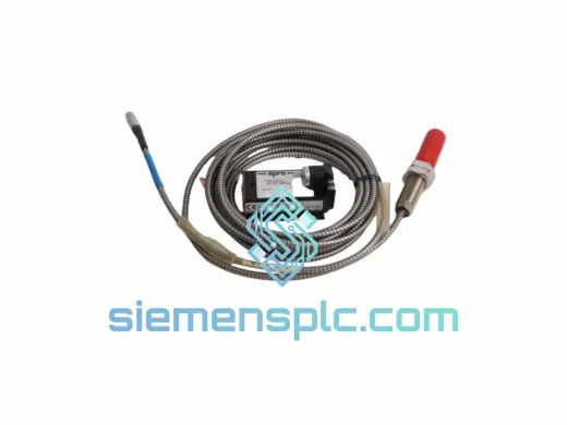
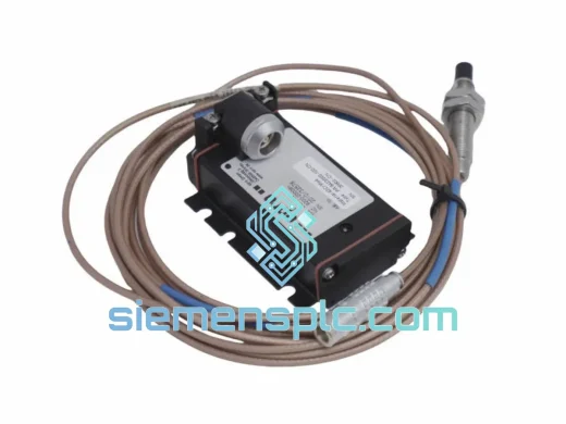
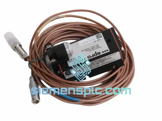
EPRO PR9268/302-000 Velocity Sensor – PR9268 Series
PR9268 Series
Origin DE
Velocity Sensor
Request verified availability, condition, replacement risk review, packing options and courier lead time for MMS6211.
Click Request Quote and the part number is inserted into the inquiry form automatically.
Core fields for model confirmation and RFQ routing. Detailed product narrative remains below.
Within a machinery protection rack, the signal-conditioning tier is where measurement fidelity and trip determinism are either secured or permanently compromised. The EPRO MMS6211 occupies that tier inside the MMS 6000 modular system, accepting raw transducer signals from two independent bearing measurement planes and executing all conditioning, scaling, alarm comparison, and output driving functions on a single Eurocard. The card’s design philosophy prioritizes hardware-enforced response time over software flexibility — a deliberate trade-off that aligns with the requirements of API 670 5th Edition and IEC 61511 safety instrumented system frameworks, where a missed or delayed trip on a high-speed compressor or steam turbine carries consequences measured in equipment replacement cost and unplanned downtime, not merely process deviation.
The MMS6211 accepts three distinct transducer classes on each channel without requiring a card swap: eddy-current proximity probes for shaft relative displacement, velocity transducers for absolute bearing housing motion, and IEPE/ICP accelerometers for high-frequency structural analysis. Channel type is selected via front-panel DIP switch and confirmed through the MMS 6000 configuration software, which writes the selection to non-volatile card memory. This means a single spare card covers the full range of measurement technologies deployed across a plant’s rotating equipment fleet — a meaningful reduction in spare parts inventory carrying cost for maintenance departments managing dozens of machine trains.
Each channel produces a 4–20 mA analog output loop that maps linearly to the configured engineering-unit range, suitable for direct termination at DCS analog input cards. Simultaneously, the card transmits full-resolution process values, alarm states, and self-diagnostic registers over the MMS 6000 backplane bus using Modbus RTU or PROFIBUS DP protocol — both active concurrently. This parallel output architecture means the DCS historian receives continuous trend data while the safety PLC receives the same measurement through a deterministic fieldbus path, with no output loading interaction between the two circuits.
Alarm architecture on the MMS6211 follows a two-tier model: an Alert setpoint for early warning and a Danger setpoint for protective trip initiation. Each tier drives an independent relay output with selectable latching or non-latching behavior. Hysteresis bands are independently configurable per setpoint to prevent relay chatter during machinery coast-down events, where vibration amplitude may oscillate across a threshold as rotational speed decreases through resonance zones. The relay driver circuit uses a normally-energized, fail-safe topology — loss of card power or detection of an internal hardware fault de-energizes the relay and drives the downstream trip logic to its safe state, consistent with de-energize-to-trip SIS design practice.
The card’s frequency response spans 0.5 Hz to 10 kHz, with the upper limit governed by the selected transducer type and the anti-aliasing filter cutoff configured for each channel. This range covers the full spectrum of rotating machinery vibration phenomena: sub-synchronous instabilities in fluid-film bearings (typically 0.3–0.48× running speed), synchronous unbalance response (1×), mechanical looseness harmonics (2× and above), and high-frequency blade-pass or gear-mesh frequencies in the kilohertz range. A single card therefore serves both low-speed reciprocating compressors and high-speed centrifugal stages without hardware modification.
Electrical isolation between the field transducer circuit and the rack backplane logic ground is implemented through a galvanic isolation barrier rated at 500 V AC continuous. This barrier suppresses ground-loop currents that arise when transducer cable shields are grounded at both the machine casing and the rack enclosure — a common installation condition in older plants where cable routing passes through multiple electrical zones. Without this isolation, 50/60 Hz interference injected through ground loops can mask low-amplitude vibration signals or generate spurious alarm conditions that erode operator confidence in the protection system.
The 16-bit sigma-delta ADC architecture provides a dynamic range of approximately 96 dB, sufficient to resolve vibration amplitudes at the lower end of the configured measurement range while simultaneously capturing full-scale excursions without clipping. Oversampling and digital decimation filtering inherent to the sigma-delta topology suppress quantization noise below the measurement floor, eliminating the need for external signal averaging that would introduce latency into the alarm response path.
Real-time Stock & RFQ: [email protected] | WhatsApp: +86 18359268345
| Parameter | Specification |
|---|---|
| Part Number | MMS6211 |
| Manufacturer | EPRO (Baker Hughes / Bently Nevada ecosystem compatible) |
| Series | MMS 6000 Modular Machinery Protection System |
| Monitoring Channels | 2, fully independent |
| Supported Transducer Types | Eddy-current proximity probe; velocity transducer; IEPE/ICP accelerometer |
| Displacement Measurement Range | 0 – 2,000 µm pk-pk (probe gap dependent) |
| Velocity Measurement Range | 0 – 200 mm/s RMS |
| Acceleration Measurement Range | 0 – 200 m/s² pk (IEPE mode) |
| Frequency Response | 0.5 Hz – 10 kHz (configuration and transducer dependent) |
| ADC Resolution | 16-bit sigma-delta |
| Analog Output | 4–20 mA, one isolated loop per channel; short-circuit protected |
| Digital Communication | Modbus RTU / PROFIBUS DP via MMS 6000 backplane bus |
| Alarm Outputs | Alert + Danger relay per channel; normally energized; latching/non-latching selectable |
| Alarm Hysteresis | Independently configurable per setpoint |
| Galvanic Isolation | 500 V AC continuous, field-to-backplane |
| Supply Voltage | 24 V DC via MMS 6000 backplane (IEC 61131-2) |
| Power Consumption | ≤ 4 W per card |
| Operating Temperature | −20 °C to +70 °C |
| Storage Temperature | −40 °C to +85 °C |
| Relative Humidity | 5 % – 95 % RH, non-condensing |
| Protection Rating | IP20 (rack-mounted Eurocard) |
| Card Format | Eurocard 100 mm × 233 mm, MMS 6000 slot-compatible |
| EMC Compliance | CE — EMC Directive 2014/30/EU; EN 61000-4-2/3/4/5/6 |
| Functional Safety | IEC 61511 SIL 1 / SIL 2 assessed; API 670 5th Edition aligned |
| RoHS | Directive 2011/65/EU compliant |
| Warranty | 12 months from confirmed shipment date |
The MMS6211’s input stage presents a high-impedance differential receiver to the transducer cable, with common-mode rejection rated to ±200 V. This specification is not conservative margin — it reflects the actual common-mode voltages measurable on proximity probe cables routed through cable trays shared with 480 V motor power conductors in typical turbine hall installations. The differential topology rejects this interference at the input stage before it can enter the signal chain, rather than relying on post-ADC digital filtering to remove it after the fact.
Alarm threshold comparison is implemented in dedicated FPGA logic rather than a shared microcontroller executing a sequential scan. Each ADC conversion result is presented to the FPGA comparator within the same clock cycle, producing a relay drive decision within one conversion period — typically under 1 ms at the card’s operating sample rate. This architecture eliminates the scan-cycle latency inherent in software-based alarm processing, where a threshold crossing occurring immediately after a scan boundary must wait a full scan period before the alarm output changes state. For a 10,000 RPM compressor, one scan period at 100 ms represents 16.7 shaft revolutions — sufficient for a developing rub to progress from contact to catastrophic seal failure.
The backplane communication interface uses transformer-coupled isolation to separate the card’s field-side analog ground from the rack’s digital logic ground. This prevents the backplane bus from acting as a low-impedance return path for field-side transient currents, which would otherwise modulate the digital supply rail and introduce switching noise into adjacent cards’ analog measurement circuits. The isolation transformer’s leakage inductance is tuned to present high impedance to the frequency range of common switching transients (10 kHz – 1 MHz) while maintaining low impedance at the Modbus/PROFIBUS communication frequencies.
The 4–20 mA output driver incorporates an active current-limiting circuit that clamps output current to 22 mA under short-circuit conditions, protecting both the card output stage and the receiving DCS input card from damage during cable fault events. The driver is loop-powered compatible, meaning it can source the loop current from the card’s internal 24 V supply without requiring an external loop power supply at the DCS termination panel — a wiring simplification that reduces installation cost on large machine trains with many monitored bearing positions.
Each MMS6211 unit dispatched from our Xiamen, China facility is sourced through traceable industrial automation supply channels with documentation linking the unit serial number to EPRO factory production records. Pre-shipment inspection covers physical condition verification against EPRO cosmetic standards, firmware version confirmation against the current release matrix, label legibility and part number accuracy check, functional power-on test within an MMS 6000 backplane with relay output verification, and anti-static packaging with desiccant and humidity indicator card. A Certificate of Conformance accompanies every shipment, and serial number traceability records are retained for a minimum of five years to support warranty claims and regulatory audits.
International logistics from Xiamen are executed via DHL Express and FedEx International Priority, with typical transit times of 3–5 business days to Europe and North America, 2–4 business days to Southeast Asia, and 5–8 business days to South America and the Middle East. For plant-down emergency situations, same-day air freight booking is available for orders confirmed before 14:00 CST. Export documentation — commercial invoice, packing list, and HS Code 9031.80 classification — is prepared in-house by our logistics team to minimize customs clearance delays at destination. All shipments carry full declared-value insurance and end-to-end tracking with proactive exception notification.
Email: [email protected]
WhatsApp: +86 18359268345
Web: siemensplc.com
Location: Xiamen, China
© 2026 siemensplc.com. All rights reserved.
We check the full part number, brand, series and visible nameplate information before quotation.
Sales confirms stock path, condition option, quantity and realistic lead time for export dispatch.
DHL, FedEx, UPS or buyer courier arrangements can be reviewed with packing requirements.
Similar brand or category products for fast comparison and multi-item RFQ lists.