Fanuc
RFQ Ready
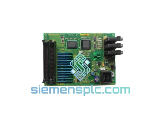
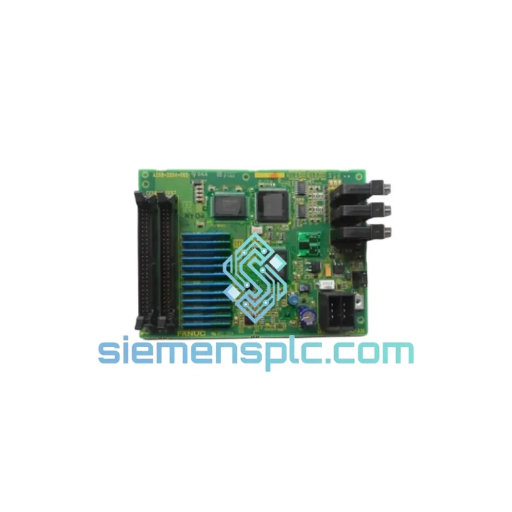
FANUC A20B-2004-038 Printed Circuit Board
Precision Control
Origin JP
Printed Circuit Board
Request verified availability, condition, replacement risk review, packing options and courier lead time for A20B-2200-0321.
Click Request Quote and the part number is inserted into the inquiry form automatically.
Core fields for model confirmation and RFQ routing. Detailed product narrative remains below.
The FANUC A20B-2200-0321 is the primary axis control printed circuit board deployed within FANUC 0-Series CNC systems — specifically the 0-MA, 0-TA, 0-MC, and 0-TC controller variants. Its function is not peripheral: this board sits at the intersection of the interpolation engine and the servo drive interface, translating numerical trajectory commands into time-stamped, position-corrected pulse trains delivered to each axis servo amplifier. Without a fully operational A20B-2200-0321, the CNC system cannot execute coordinated multi-axis motion, rendering the machine inoperable regardless of the condition of other subsystems.
In a FANUC 0-Series control cabinet, the CPU board generates interpolated position data at the system clock rate. The A20B-2200-0321 receives this data via the backplane bus, applies real-time error compensation derived from encoder feedback, and outputs differential pulse commands to the servo amplifier modules. The board also manages the position error register — the accumulator that tracks the delta between commanded and actual axis position — and triggers alarm states when deviation exceeds the configured in-position tolerance window. This makes the A20B-2200-0321 a deterministic real-time processor, not a general-purpose controller.
Real-time Stock & RFQ: [email protected] | WhatsApp: +86 18359268345
| Parameter | Specification |
|---|---|
| Part Number | A20B-2200-0321 |
| Compatible Controller Series | FANUC 0-Series (0-MA, 0-TA, 0-MC, 0-TC) |
| Board Function | Axis Control PCB / Servo Interface & Position Error Management |
| Form Factor | Single-slot PCB, rack-mount, FANUC 0-Series backplane compatible |
| Bus Interface | FANUC proprietary parallel backplane bus (0-Series standard) |
| Encoder Feedback Interface | Differential TTL pulse input, A/B/Z phase, compatible with FANUC αi/βi and legacy pulse encoders |
| Servo Command Output | Differential pulse train output per axis channel |
| Position Error Register | 32-bit accumulator per axis; configurable in-position tolerance |
| Operating Voltage | +5 VDC, ±12 VDC (supplied via backplane) |
| Operating Temperature | 0°C to +55°C (ambient, forced-air cooled cabinet) |
| Storage Temperature | -20°C to +60°C |
| Humidity | 5% to 95% RH, non-condensing |
| PCB Weight | 323 g |
| Manufacturer | FANUC Corporation, Japan |
| Country of Origin | Japan |
| Warranty | 12 months functional warranty from dispatch date |
| Lead Time | In stock — ships within 1–3 business days from Xiamen, China |
The A20B-2200-0321 implements several hardware-level design decisions that distinguish it from generic motion control PCBs:
Backplane Bus Arbitration: The board communicates with the FANUC 0-Series CPU via a synchronous parallel bus operating at the system interpolation cycle rate (typically 8 ms for standard 0-Series, 4 ms for high-speed variants). The A20B-2200-0321 acts as a bus slave, latching position commands on each cycle edge and immediately loading them into the pulse distribution circuit. This synchronous architecture eliminates jitter introduced by asynchronous communication protocols, which is critical for maintaining contouring accuracy in multi-axis interpolation.
Pulse Distribution Circuit (PDC): The on-board PDC converts interpolated position increments into discrete pulse trains using a hardware accumulator-comparator structure. Each axis channel maintains an independent accumulator; when the accumulated value exceeds the pulse equivalent (typically 1 µm or 0.001° depending on machine configuration), a command pulse is issued to the servo amplifier. This hardware implementation ensures pulse timing is not subject to software scheduling latency.
EMC Design: The PCB layout follows FANUC’s established ground-plane partitioning strategy: the digital logic section (bus interface, accumulators, control logic) and the analog/differential signal section (encoder input receivers, servo command output drivers) are separated by a continuous ground plane split, with signal crossings routed through filtered vias. Differential line drivers and receivers on encoder inputs provide common-mode noise rejection exceeding 30 dB, which is necessary in cabinet environments where servo amplifier switching transients can reach several hundred millivolts on the ground reference.
Position Error Register & Alarm Logic: Each axis channel on the A20B-2200-0321 maintains a hardware position error register that accumulates the difference between commanded pulses issued and encoder feedback pulses received. If this register exceeds the configured SV023 (position error limit) parameter, the board asserts a servo alarm signal directly on the backplane, triggering an emergency stop without waiting for a software polling cycle. This hardware-level alarm assertion reduces the worst-case response time from a software-polled ~8 ms to a hardware-asserted sub-1 ms, limiting potential mechanical damage during runaway conditions.
Component-Level Reliability: FANUC specifies industrial-grade ceramic capacitors and metal-film resistors in the signal path of the A20B-2200-0321, avoiding electrolytic capacitors in timing-critical circuits. This design choice extends the board’s service life in high-temperature cabinet environments where electrolytic capacitor ESR degradation is the primary failure mode for legacy PCBs.
Every A20B-2200-0321 unit processed through our Xiamen facility undergoes a structured inspection and verification sequence before dispatch:
Logistics from Xiamen, China covers global destinations via DHL Express, FedEx International Priority, and UCP air freight for volume orders. Standard transit times: 3–5 business days to Europe and North America, 2–4 business days to Southeast Asia. Export documentation including commercial invoice, packing list, and certificate of origin is prepared for all international shipments. Buyers are responsible for import duties and compliance with local import regulations.
Email: [email protected]
WhatsApp: +86 18359268345
Web: siemensplc.com
Location: Xiamen, China
© 2026 siemensplc.com. All rights reserved.
We check the full part number, brand, series and visible nameplate information before quotation.
Sales confirms stock path, condition option, quantity and realistic lead time for export dispatch.
DHL, FedEx, UPS or buyer courier arrangements can be reviewed with packing requirements.
Similar brand or category products for fast comparison and multi-item RFQ lists.