Fuji Electric
RFQ Ready
FUJI Electric NP1X3206-W PLC Power Supply Module
NP1 Series
Origin Japan
PLC Power Supply Module
Request verified availability, condition, replacement risk review, packing options and courier lead time for 7MBI40N-120.
Click Request Quote and the part number is inserted into the inquiry form automatically.
Core fields for model confirmation and RFQ routing. Detailed product narrative remains below.
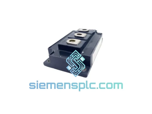
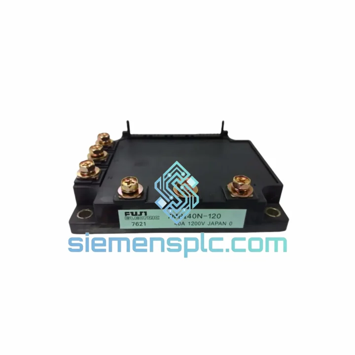
The Fuji Electric 7MBI40N-120 is a six-pack (6-in-1) IGBT power module rated at 40 A continuous collector current and 1200 V collector-emitter blocking voltage. The device integrates six IGBT chips and six co-packaged freewheeling diodes in a complete three-phase bridge topology within a single molded N-Series housing. This architecture eliminates the need for external discrete switching devices in the inverter stage, reducing PCB footprint by approximately 40% relative to equivalent discrete implementations and lowering total stray inductance in the DC-link commutation loop.
In a closed-loop vector control or V/f drive architecture, the 7MBI40N-120 sits between the DC bus capacitor bank and the motor terminals. Gate signals generated by a DSP or FPGA-based PWM controller are routed to each of the six gate-emitter terminals through isolated gate driver ICs. The internal topology places the upper and lower switches of each phase leg on a shared emitter reference per leg, which simplifies bootstrap gate driver design and reduces shoot-through susceptibility under high dV/dt transients. The module is characterized for switching frequencies from 2 kHz to 16 kHz, covering both low-frequency high-torque applications — crane hoists, extruders, pump drives — and high-frequency low-acoustic-noise applications such as HVAC compressors and servo spindles.
The 7MBI40N-120 is built on Fuji Electric’s fourth-generation NPT (Non-Punch-Through) IGBT cell process. NPT devices exhibit a positive temperature coefficient of collector-emitter saturation voltage VCE(sat), which provides inherent static current-sharing stability when two or more modules are operated in parallel on the same phase leg — a property essential for drive platforms above 75 kW. The positive coefficient also means that a module approaching thermal stress will draw proportionally less current than a cooler parallel unit, preventing thermal runaway cascades without active current balancing circuitry.
The integrated freewheeling diodes are co-optimized with the IGBT chips for controlled soft-recovery behavior. Reverse recovery charge Qrr is minimized to reduce the current overshoot in the complementary IGBT during turn-on transitions. In a 400 V DC-bus application at 8 kHz switching frequency, total module switching losses are typically below 35 W at rated current, enabling compact heatsink designs with natural convection in sub-15 kW inverter enclosures. For forced-air cooled systems, the thermal budget allows sustained operation at 40 A with a case temperature up to 97 °C, providing a 53 °C margin to Tj,max at the rated Rth(j-c).
Real-time Stock & RFQ: [email protected] | WhatsApp: +86 18359268345
| Parameter | Symbol | Specification | Test Condition |
|---|---|---|---|
| Collector-Emitter Blocking Voltage | VCES | 1200 V | Tj = 25 °C, VGE = 0 V |
| Gate-Emitter Voltage (Absolute Max) | VGES | ±20 V | DC, continuous |
| Continuous Collector Current | IC | 40 A | Tc = 25 °C |
| Pulsed Collector Current | ICP | 80 A | Tj ≤ 150 °C, tp ≤ 1 ms |
| Collector-Emitter Saturation Voltage (typ.) | VCE(sat) | 2.0 V (max 2.5 V) | IC = 40 A, VGE = +15 V, Tj = 25 °C |
| Gate Threshold Voltage | VGE(th) | 5.0 – 7.0 V | IC = 1 mA, VCE = VGE |
| Turn-On Delay Time | td(on) | ≈ 0.5 µs | Inductive load, VGE = ±15 V, RG = 10 Ω |
| Rise Time | tr | ≈ 0.3 µs | Same conditions |
| Turn-Off Delay Time | td(off) | ≈ 1.2 µs | Same conditions |
| Fall Time | tf | ≈ 0.4 µs | Same conditions |
| Short-Circuit Withstand Time | tsc | ≥ 10 µs | VCC = 800 V, Tj = 125 °C |
| Junction Temperature (Operating) | Tj | −40 °C to +150 °C | — |
| Storage Temperature | Tstg | −40 °C to +125 °C | — |
| Isolation Voltage (RMS, 1 min) | Visol | 2500 V AC | Baseplate to all terminals |
| Thermal Resistance, Junction-to-Case (per IGBT) | Rth(j-c) | ≤ 0.83 °C/W | Per switch element |
| Thermal Resistance, Case-to-Heatsink | Rth(c-s) | ≤ 0.20 °C/W | With thermal compound, λ ≥ 1.0 W/m·K |
| Recommended PWM Frequency Range | fsw | 2 – 16 kHz | Derate IC above 8 kHz per datasheet curve |
| Module Weight | — | ≈ 380 g | — |
| Mounting Torque (M5 screws) | — | 3.0 – 4.0 N·m | Baseplate to heatsink |
| Warranty | — | 12 months | From shipment date, genuine Fuji Electric origin |
NPT Cell Architecture and Thermal Stability: The fourth-generation NPT IGBT process used in the 7MBI40N-120 eliminates the heavily doped buffer layer present in punch-through devices. This structural choice produces a wider lightly-doped N-drift region, which increases the positive temperature coefficient of VCE(sat) from approximately +0.5 mV/°C in PT devices to +1.5 mV/°C in NPT devices at rated current. The practical consequence is that a module operating at elevated junction temperature will present a higher on-state voltage drop, causing the parallel current to redistribute toward the cooler module — a passive balancing mechanism that requires no external sensing or control logic.
Gate Loop Inductance and EMC Performance: The N-Series package routes signal leads (gate and Kelvin emitter) through a dedicated low-inductance path physically separated from the power terminals (collector bus bars and AC output terminals). This separation reduces mutual inductance between the gate signal loop and the DC-link commutation loop to below 20 nH. At a di/dt of 500 A/µs during hard turn-on, the induced gate voltage spike is limited to below 10 V — well within the ±20 V absolute maximum gate rating — without requiring external gate resistor values above 10 Ω. The reduced gate ringing also lowers radiated EMI in the 150 kHz–30 MHz band, easing compliance with EN 61800-3 Category C2 conducted and radiated emission limits.
DBC Substrate and Thermal Interface Geometry: The chip-to-baseplate thermal path uses a Direct Bonded Copper (DBC) substrate with an aluminum nitride (AlN) ceramic dielectric layer. AlN provides a thermal conductivity of approximately 170 W/m·K, compared to 24 W/m·K for standard alumina (Al₂O₃) substrates. This 7× improvement in ceramic conductivity reduces the substrate thermal resistance contribution to the overall Rth(j-c) budget, allowing the module to achieve ≤ 0.83 °C/W per switch despite the six-chip integration density. The copper baseplate is nickel-plated and lapped to a flatness tolerance of ≤ 50 µm, ensuring uniform thermal compound distribution across the full mounting surface when torqued to specification.
Freewheeling Diode Reverse Recovery Optimization: The co-packaged diodes are processed with controlled carrier lifetime to achieve a soft-recovery characteristic. The peak reverse recovery current Irr is limited to approximately 20 A under standard test conditions (IF = 40 A, dIF/dt = 200 A/µs, VR = 600 V). This controlled Irr reduces the current overshoot in the complementary IGBT during turn-on, which is the dominant source of turn-on switching energy Eon in hard-switched inverter topologies. The result is a measurable reduction in total inverter losses at switching frequencies above 4 kHz compared to modules using standard-recovery diodes.
Short-Circuit Robustness: The device is characterized for a short-circuit withstand time tsc ≥ 10 µs at VCC = 800 V and Tj = 125 °C. This specification defines the fault detection window available to the gate driver’s desaturation (DESAT) protection circuit. Gate drivers with DESAT response times below 3 µs provide a 7 µs safety margin — sufficient for the gate driver to clamp the gate voltage to zero and allow the collector current to fall through the IGBT’s natural turn-off characteristic without exceeding the safe operating area (SOA) boundary.
All 7MBI40N-120 units supplied through siemensplc.com are sourced as genuine Fuji Electric production stock with full manufacturer traceability. Inventory is held in a climate-controlled warehouse in Xiamen, China, maintained at 20–25 °C and 40–60% relative humidity to preserve solder joint integrity and DBC substrate bond layer adhesion over extended storage periods. Each unit undergoes a pre-dispatch inspection covering package integrity, terminal surface condition, and date-code legibility. Electrical screening — including VCE(sat) spot-check at rated gate drive and isolation resistance measurement at 500 V DC — is available on request for orders of five units or more.
Packaging uses conductive foam trays inside double-wall corrugated cartons with silica gel desiccant and a humidity indicator card. Batch traceability documentation — manufacturer lot number, date code, and country of origin certificate — accompanies every shipment. Export from Xiamen is handled via DHL Express, FedEx International Priority, and UPS Worldwide Expedited, with typical door-to-door transit times of 3–5 business days to Europe, North America, the Middle East, and Southeast Asia. Air freight consolidation is available for orders exceeding 20 kg gross weight. All commercial invoices include HS Code 8541.10 and a detailed packing list formatted for customs clearance in major import markets including the EU, USA, Japan, and Australia.
A 12-month warranty from the date of shipment covers manufacturing defects under normal operating and storage conditions. Warranty claims are processed with RMA authorization within 48 hours of receipt of the defective unit and supporting documentation, including installation photographs, drive fault log extracts, and a thermal interface condition report.
Email: [email protected]
WhatsApp: +86 18359268345
Web: siemensplc.com
Location: Xiamen, China
© 2026 siemensplc.com. All rights reserved.
We check the full part number, brand, series and visible nameplate information before quotation.
Sales confirms stock path, condition option, quantity and realistic lead time for export dispatch.
DHL, FedEx, UPS or buyer courier arrangements can be reviewed with packing requirements.
Similar brand or category products for fast comparison and multi-item RFQ lists.