Fuji Electric
RFQ Ready
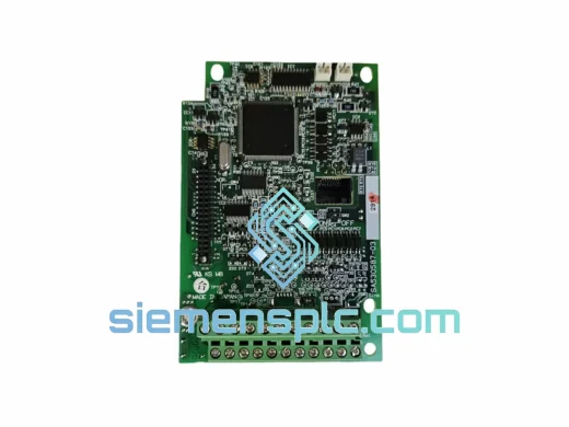
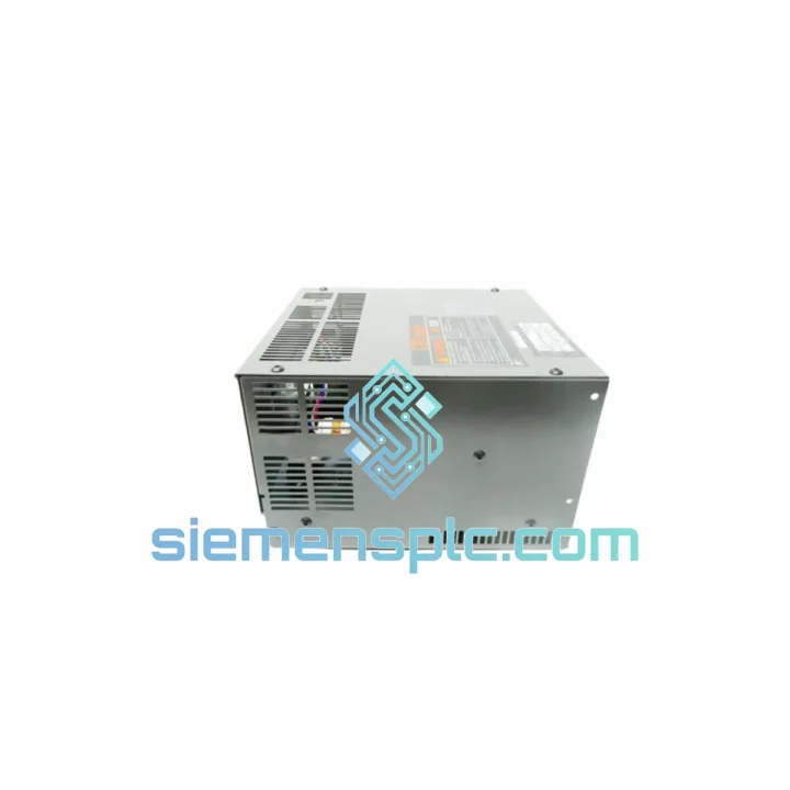
FUJI Electric EP-3531D C1-Z1 Inverter Control Board
P-3531D C1-Z1 FRENIC Series
Origin Japan
Inverter Drive Control Board
Request verified availability, condition, replacement risk review, packing options and courier lead time for BU55-4C.
Click Request Quote and the part number is inserted into the inquiry form automatically.
Core fields for model confirmation and RFQ routing. Detailed product narrative remains below.
The BU55-4C is a dedicated dynamic braking unit manufactured by Fuji Electric, designed to operate in conjunction with FRENIC-series variable frequency drives at the 55 kW / 400 V class. Its primary function is to clamp DC bus voltage during motor deceleration phases by routing regenerative energy through an external braking resistor, converting kinetic energy into heat and preventing DC bus overvoltage faults that would otherwise trip the drive. This unit is not a passive component — it contains an integrated IGBT chopper transistor with its own gate drive circuitry, thermal monitoring, and fault output logic, making it a discrete power electronics assembly within the drive system architecture.
In high-inertia applications — crane hoists, centrifuges, winding machines, and test dynamometers — the motor transitions from motoring to generating mode during deceleration. The regenerated current flows back into the drive’s DC bus, raising bus voltage. Without active clamping, the bus voltage climbs until the drive’s OV protection threshold is reached, causing a fault trip. The BU55-4C monitors DC bus voltage continuously and activates its internal IGBT when the bus exceeds approximately 760 V DC, diverting current through the external resistor. The chopper switches at high frequency to maintain bus voltage within a controlled band, allowing the drive to complete the deceleration ramp without interruption.
Real-time Stock & RFQ: [email protected] | WhatsApp: +86 18359268345
| Parameter | Specification |
|---|---|
| Model Number | BU55-4C |
| Manufacturer | Fuji Electric Co., Ltd. |
| Compatible Series | FRENIC-Multi, FRENIC-Ace, FRENIC-MEGA |
| Applicable Drive Capacity | 55 kW (400 V class) |
| Input Voltage Class | 3-Phase 380–480 V AC |
| DC Bus Operating Range | 500–820 V DC |
| IGBT Activation Threshold | Approx. 760 V DC |
| Braking Transistor Type | Built-in IGBT with integrated gate driver |
| Standard Braking Duty Cycle | 10% ED (continuous duty requires derating — consult datasheet) |
| External Braking Resistor | Required (not included); minimum resistance per Fuji sizing table |
| Enclosure Protection | IP00 (open chassis, panel-mount installation) |
| Cooling Method | Forced air via internal fan |
| Ambient Operating Temperature | -10°C to +50°C |
| Storage Temperature | -20°C to +65°C |
| Approximate Weight | 3.5 kg |
| Country of Origin | Japan |
| Warranty | 12 months from date of shipment |
| Compliance | CE (LVD 2014/35/EU), RoHS, IEC 61800-5-1 |
The BU55-4C is built around a single high-voltage IGBT module rated for the peak current demands of a 55 kW regenerative event. The gate driver circuit is isolated from the control logic via an optocoupler barrier, which serves two purposes: it protects the low-voltage control circuitry from DC bus transients, and it ensures that gate drive timing is not corrupted by common-mode noise on the bus — a critical design consideration in environments with long motor cables or adjacent switching equipment.
The DC bus voltage is sampled by a resistive voltage divider feeding a comparator circuit. The comparator reference is set to correspond to the 760 V DC activation threshold. When bus voltage crosses this threshold, the comparator output triggers the gate driver, turning on the IGBT and connecting the external braking resistor across the DC bus. The IGBT switches at a fixed or variable duty cycle to regulate the average power dissipated in the resistor, maintaining bus voltage within a defined window above the activation threshold. This hysteresis band prevents rapid on-off cycling that would stress the IGBT junction.
Thermal management is handled by an NTC thermistor bonded to the IGBT module baseplate. If junction temperature approaches the rated limit, the unit asserts a fault output signal that can be wired to the drive’s external fault input terminal, triggering a controlled drive shutdown rather than an uncontrolled thermal failure. The forced-air fan is thermally activated in some configurations, reducing acoustic noise during light-load operation while ensuring adequate airflow during sustained braking events.
The DC bus connection terminals are sized for the cable cross-sections appropriate to 55 kW at 400 V class, with clearly marked polarity. The unit does not include internal fusing on the DC bus connection — the system designer must provide appropriately rated DC fuses or a circuit breaker upstream of the BU55-4C to protect against resistor short-circuit faults. This is consistent with standard industrial panel design practice and allows the protection device to be selected based on the specific installation’s fault current capacity.
EMC performance is addressed through the PCB layout, which minimizes the loop area of the high-frequency switching current path. The gate drive traces are routed away from the voltage sensing circuitry to reduce capacitive coupling. The unit does not include an internal EMC filter on the DC bus — this is appropriate since the DC bus is an internal node of the drive system and EMC filtering is handled at the AC input of the drive itself.
Every BU55-4C unit supplied by siemensplc.com is sourced through verified industrial distribution channels and carries full Fuji Electric OEM traceability. Prior to dispatch from our Xiamen, China facility, each unit undergoes visual inspection against Fuji Electric original packaging standards, label and serial number verification, and a continuity check on the DC bus terminals and fault output wiring. No refurbished, grey-market, or counterfeit components are handled or supplied.
Xiamen’s geographic position — a major port city in Fujian Province with direct access to international freight routes — enables competitive transit times to Southeast Asia (2–5 days), Europe (5–10 days), and North America (7–14 days) via DHL, FedEx, and UPS express services. For bulk project orders, sea freight consolidation is available with full commercial invoice and packing list documentation for customs clearance. All shipments include tracking and are covered by our 12-month warranty from the date of shipment. Warranty claims are processed with replacement unit dispatch or full refund at the buyer’s election.
Email: [email protected]
WhatsApp: +86 18359268345
Web: siemensplc.com
Location: Xiamen, China
© 2026 siemensplc.com. All rights reserved.
We check the full part number, brand, series and visible nameplate information before quotation.
Sales confirms stock path, condition option, quantity and realistic lead time for export dispatch.
DHL, FedEx, UPS or buyer courier arrangements can be reviewed with packing requirements.
Similar brand or category products for fast comparison and multi-item RFQ lists.