Fuji Electric
RFQ Ready
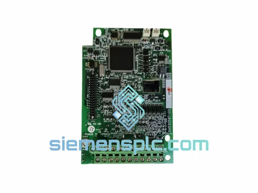
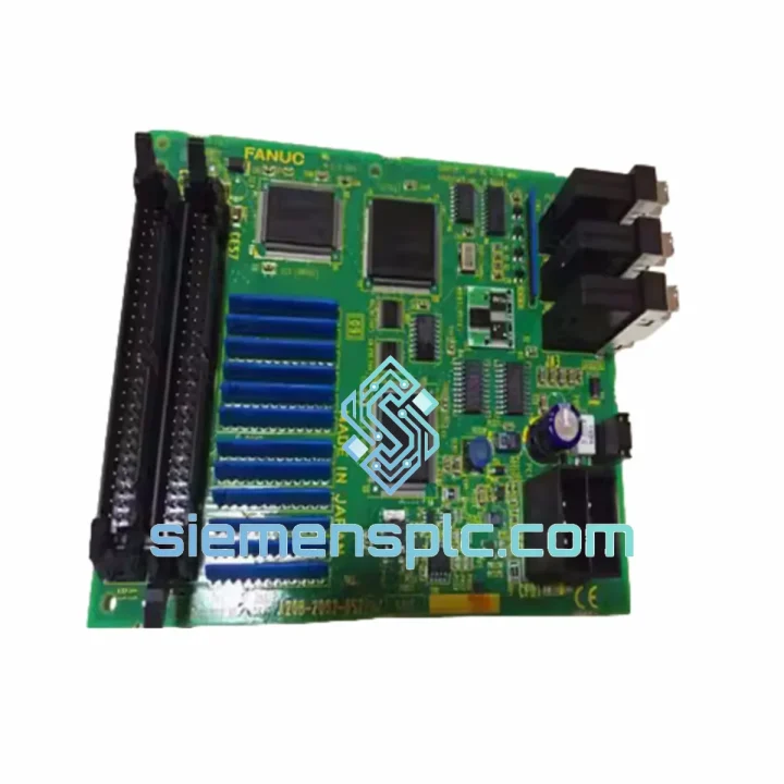
FUJI Electric EP-3531D C1-Z1 Inverter Control Board
P-3531D C1-Z1 FRENIC Series
Origin Japan
Inverter Drive Control Board
Request verified availability, condition, replacement risk review, packing options and courier lead time for G9-CPCB.
Click Request Quote and the part number is inserted into the inquiry form automatically.
Core fields for model confirmation and RFQ routing. Detailed product narrative remains below.
The G9-CPCB SA518973-04 is the dedicated main control circuit board for the Fuji Electric G9 Series variable frequency drive (VFD) platform. Within the drive’s internal hierarchy, this PCB occupies the top layer of the signal-processing chain: it receives analog and digital command inputs, executes the V/f or vector control algorithm, generates PWM gate-drive signals for the IGBT power stage, and manages all fault detection, protection relay logic, and operator interface communication. Without a fully functional control board, the power stage of any G9 Series inverter is inert — no switching sequence can be generated, no motor current can be regulated, and no protective interlock can be enforced.
In practical terms, the SA518973-04 revision of this board governs the entire closed-loop control architecture of the G9 drive. Its onboard DSP executes the current-vector decomposition algorithm at a fixed carrier frequency cycle, translating the torque and flux reference signals into six-channel IGBT gate commands with sub-microsecond timing resolution. The analog input conditioning circuitry — comprising precision op-amp stages and 12-bit ADC sampling — converts 0–10 V or 4–20 mA speed-reference signals into digital setpoints with a linearity error of less than ±0.2% of full scale. This level of signal fidelity is non-negotiable in tension-controlled web processes and closed-loop pump pressure regulation.
Real-time Stock & RFQ: [email protected] | WhatsApp: +86 18359268345
| Part Number | SA518973-04 |
| Assembly Code | G9-CPCB |
| Manufacturer | Fuji Electric Co., Ltd. |
| Compatible Series | Fuji Electric G9 Series VFD (FRN□□□G9S-□□□) |
| Component Classification | Main Control Circuit Board (PCB) |
| Control Method Support | V/f control, sensorless vector control, closed-loop vector control |
| Analog Input Resolution | 12-bit ADC; 0–10 V / 4–20 mA reference inputs |
| Analog Input Linearity | ±0.2% of full scale (typical) |
| Digital I/O | Multi-function programmable digital inputs (sink/source selectable); relay output contacts rated 250 VAC / 1 A |
| Communication Interface | RS-485 (Modbus RTU); optional fieldbus expansion via plug-in card slot |
| Operator Panel Interface | Dedicated keypad connector (RJ-type); supports remote panel extension |
| PWM Output Channels | 6-channel gate drive signal output to IGBT power module |
| Protection Functions | Overcurrent (OC), overvoltage (OV), undervoltage (UV), overtemperature (OH), ground fault (GF), output phase loss |
| Operating Temperature | –10 °C to +50 °C (ambient, with derating above 40 °C) |
| Storage Temperature | –25 °C to +65 °C |
| Humidity | 5–95% RH, non-condensing |
| Vibration Resistance | 5.9 m/s² (0.6 G), 10–55 Hz per IEC 60068-2-6 |
| PCB Surface Finish | Conformal coating (acrylic-based) on signal-layer traces |
| Country of Origin | Japan |
| Shipping Weight | 4,460 g |
| Warranty | 12 months from date of shipment |
The G9-CPCB SA518973-04 implements several hardware-level design decisions that distinguish it from generic replacement boards available in the aftermarket.
Galvanic Isolation Architecture: The boundary between the high-voltage power stage and the low-voltage control logic is enforced through optocoupler-based galvanic isolation on every gate-drive signal path. Each of the six IGBT gate channels passes through a dedicated high-speed optocoupler (typical propagation delay <1 µs), ensuring that a power-stage fault — including a shoot-through event — cannot propagate destructive transients back into the DSP or analog input circuitry. The isolation barrier is rated to withstand common-mode transients in excess of 1,500 V/µs, which is consistent with the dV/dt levels generated by modern IGBT switching at carrier frequencies of 4–16 kHz.
EMC Filtering on Analog Inputs: Each analog input channel incorporates a passive RC low-pass filter with a –3 dB cutoff frequency of approximately 100 Hz, followed by a differential amplifier stage. This two-stage approach attenuates both conducted RF interference (common in switchgear-dense panels) and common-mode noise induced by long signal cable runs. The differential input topology provides a common-mode rejection ratio (CMRR) of typically 60 dB at 50/60 Hz, which is sufficient to maintain ADC accuracy in environments with significant ground potential differences between the drive cabinet and the remote speed-reference source.
Watchdog and Fault Latch Logic: The onboard microcontroller implements a hardware watchdog timer independent of the main DSP execution loop. If the DSP fails to service the watchdog within the defined timeout window — due to a software exception, memory fault, or clock anomaly — the watchdog asserts a hardware reset and simultaneously latches a fault code into non-volatile memory. This design ensures that a control board malfunction results in a safe, documented drive trip rather than an undefined output state that could damage the motor or connected machinery.
Parameter Non-Volatile Storage: All drive parameters, including acceleration/deceleration ramps, V/f curve breakpoints, PID coefficients, and protection thresholds, are stored in onboard EEPROM. The write-cycle endurance of the EEPROM is rated at a minimum of 100,000 write cycles, providing reliable parameter retention across the operational life of the drive without battery backup.
Thermal Management of Control Circuitry: The DSP and analog front-end components are positioned away from the board’s edge connectors and power supply input traces to minimize thermal coupling from the drive’s internal heat sources. The conformal coating applied to signal-layer traces provides additional protection against condensation-induced leakage currents in high-humidity environments, extending the mean time between failures (MTBF) in coastal and tropical industrial installations.
Every Fuji Electric G9-CPCB SA518973-04 unit dispatched from our Xiamen, China facility is processed through a structured pre-shipment verification protocol. Each board undergoes visual inspection under magnification for solder joint integrity, component seating, and PCB trace condition. Part number and revision markings are cross-referenced against Fuji Electric’s OEM documentation to confirm authenticity. Units are packaged in anti-static (ESD-safe) bags with foam cushioning inserts, then placed in double-wall corrugated cartons rated for international air freight handling.
Shipments originate from Xiamen and are dispatched via DHL Express, FedEx International Priority, or UPS Worldwide Expedited, depending on destination and urgency. Transit times to major industrial hubs are typically 3–5 business days to Southeast Asia, 5–7 business days to Europe and the Middle East, and 5–8 business days to North America. Full commercial invoice, packing list, and HS code documentation are provided with every shipment to facilitate customs clearance. For customers in regions with import duty sensitivity, we can advise on applicable HS codes and provide certificate of origin documentation upon request.
All units are covered by a 12-month warranty from the date of shipment. Warranty claims are handled directly by our technical team; defective units are assessed within 5 business days of receipt, and replacement dispatch follows within 3 business days of fault confirmation. We maintain buffer stock of the G9-CPCB SA518973-04 to support both immediate replacement needs and planned maintenance spare pools for customers operating multiple G9 Series drives.
Email: [email protected]
WhatsApp: +86 18359268345
Web: siemensplc.com
Location: Xiamen, China
© 2026 siemensplc.com. All rights reserved.
We check the full part number, brand, series and visible nameplate information before quotation.
Sales confirms stock path, condition option, quantity and realistic lead time for export dispatch.
DHL, FedEx, UPS or buyer courier arrangements can be reviewed with packing requirements.
Similar brand or category products for fast comparison and multi-item RFQ lists.