Fuji Electric
RFQ Ready
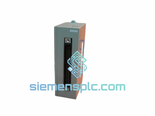
FUJI NV1Y32T05P1 PLC Digital Output Module
NV Series PLC
Origin Japan
PLC I/O Module
Request verified availability, condition, replacement risk review, packing options and courier lead time for MICREX-F.
Click Request Quote and the part number is inserted into the inquiry form automatically.
Core fields for model confirmation and RFQ routing. Detailed product narrative remains below.
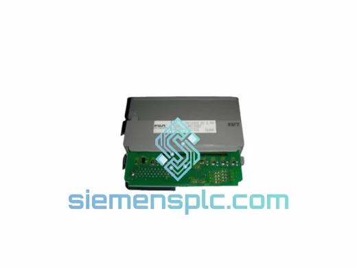
The FUJI FTM100B is a discrete transistor output module engineered for deployment within FUJI Electric’s MICREX-F programmable logic controller platform. In a distributed I/O architecture, this module occupies the output stage of the control loop: it receives resolved logic states from the CPU over the proprietary MICREX-F backplane bus and drives field-side actuators — solenoid valves, motor contactors, indicator lamps, and relay coils — with deterministic switching latency. Unlike relay output modules, the FTM100B’s solid-state transistor output stage eliminates mechanical wear, enabling sustained high-cycle operation without contact degradation. This characteristic makes it the preferred output interface in applications where output switching frequency exceeds several hundred cycles per hour or where output response time is a process-critical parameter.
Within the MICREX-F system hierarchy, the FTM100B communicates with the CPU module via the internal I/O bus embedded in the backplane. The CPU scans the output image table at each PLC scan cycle — typically in the range of 1–10 ms depending on program size — and writes resolved output states to the module’s internal latch register. The FTM100B then drives its transistor output drivers accordingly, with propagation delay from latch write to physical output state change measured in microseconds. This tight coupling between CPU scan and physical output actuation is fundamental to achieving deterministic control loop closure in time-sensitive manufacturing processes.
Real-time Stock & RFQ: [email protected] | WhatsApp: +86 18359268345
| Parameter | Specification |
|---|---|
| Manufacturer | FUJI Electric Co., Ltd. |
| Part Number / SKU | FTM100B |
| Series | MICREX-F |
| Module Category | Digital Output Module |
| Output Technology | Transistor (solid-state, NPN/PNP — verify per datasheet revision) |
| Mounting Interface | MICREX-F backplane rack slot |
| Bus Interface | FUJI MICREX-F internal I/O bus (proprietary parallel backplane) |
| Unit Weight | 4,460 g (4.46 kg) |
| Operating Temperature | 0°C to +55°C (panel-mounted, forced-air cooling recommended above 45°C) |
| Storage Temperature | -20°C to +70°C |
| Relative Humidity | 5% to 95% RH, non-condensing |
| Vibration Resistance | Compliant with IEC 60068-2-6 (10–57 Hz, 0.075 mm amplitude) |
| Dielectric Isolation | Optical isolation between field-side outputs and logic-side bus (photocoupler-based) |
| Warranty | 12 months from date of shipment |
The FTM100B’s output stage is built around a photocoupler-based galvanic isolation barrier positioned between the MICREX-F backplane logic domain (typically 5 VDC CMOS-level signals) and the field-side output domain (24 VDC load circuits). Each output channel routes through an individual LED-photodetector pair, ensuring that transient overvoltages, ground potential differences, and inductive kickback events on the field side cannot propagate into the CPU’s logic circuitry. This isolation architecture is consistent with IEC 61131-2 requirements for Type 1 and Type 3 digital output modules.
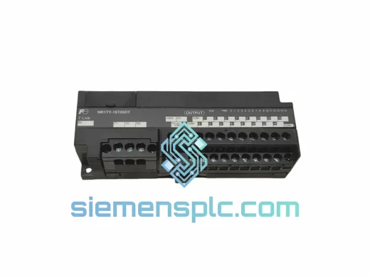
On the field side, each transistor driver incorporates a freewheeling diode or transient voltage suppressor (TVS) across the output terminals to clamp inductive load switching transients. When driving inductive loads such as solenoid coils or contactor coils, the energy stored in the load inductance (E = ½LI²) must be dissipated at turn-off; without clamping, the resulting voltage spike can exceed the transistor’s collector-emitter breakdown voltage (BVCEO). The integrated suppression network limits this transient to within the transistor’s safe operating area (SOA), extending output channel service life in inductive-load-intensive applications.
The module’s EMC design addresses both conducted and radiated interference. Conducted immunity is achieved through decoupling capacitors on the logic supply rails and common-mode chokes on the field-side wiring interface. Radiated immunity is supported by the module’s metal housing, which provides a Faraday shield effect, attenuating external RF fields that could otherwise induce spurious switching in high-impedance signal nodes. These design measures align with EN 61000-4-3 (radiated immunity) and EN 61000-4-4 (electrical fast transient/burst) test standards applicable to industrial control equipment.
The backplane bus interface logic within the FTM100B includes address decoding circuitry that maps the module to a specific I/O address range within the MICREX-F system’s I/O memory map. This addressing is established at rack configuration time and is fixed in hardware via slot position, eliminating the risk of address conflicts during hot-swap or module replacement operations — a critical reliability feature in production environments where unplanned downtime carries direct financial cost.
Every FUJI FTM100B unit dispatched from our Xiamen, China facility is sourced directly from authorized FUJI Electric distribution channels. Prior to shipment, each module undergoes a structured inspection protocol: visual examination of PCB, connector pins, housing, and label authenticity; functional output channel continuity verification; and serial number cross-referencing against FUJI Electric’s known genuine product characteristics to screen for counterfeit units — a documented risk in the secondary industrial components market.
Packaging follows anti-static and moisture-barrier standards: each module is sealed in an ESD-protective bag, placed in foam-lined rigid packaging, and enclosed in a double-wall corrugated outer carton rated for international air and sea freight handling. For time-critical requirements, DHL Express, FedEx International Priority, and UPS Worldwide Express services are available from Xiamen Gaoqi International Airport, with transit times of 3–5 business days to most destinations in Europe, North America, Southeast Asia, and the Middle East. Sea freight consolidation is available for bulk orders where lead time permits.
All shipments are accompanied by a commercial invoice, packing list, and certificate of conformity. An inspection report is available on request for customers with incoming quality control requirements. The 12-month warranty covers manufacturing defects and functional failure under normal operating conditions; warranty claims are processed with replacement dispatch within 5 business days of fault confirmation.
Email: [email protected]
WhatsApp: +86 18359268345
Web: siemensplc.com
Location: Xiamen, China
© 2026 siemensplc.com. All rights reserved.
We check the full part number, brand, series and visible nameplate information before quotation.
Sales confirms stock path, condition option, quantity and realistic lead time for export dispatch.
DHL, FedEx, UPS or buyer courier arrangements can be reviewed with packing requirements.
Similar brand or category products for fast comparison and multi-item RFQ lists.