GE Grid Solutions
RFQ Ready
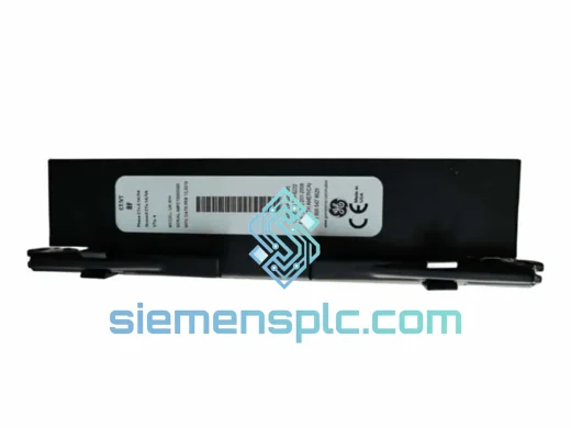
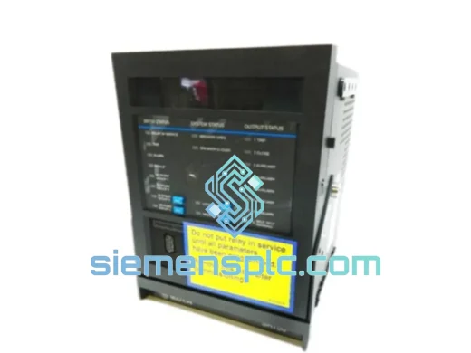
GE UR7IH Communication Module
cation Module for UR Series
Origin US
Communication Module
Request verified availability, condition, replacement risk review, packing options and courier lead time for 750-P5-G5-S5-HI-A20-R.
Click Request Quote and the part number is inserted into the inquiry form automatically.
Core fields for model confirmation and RFQ routing. Detailed product narrative remains below.
The GE 750-P5-G5-S5-HI-A20-R is a fully integrated feeder management relay from GE Grid Solutions (GE Multilin), engineered for deterministic overcurrent protection, metering, and supervisory control on medium-voltage distribution feeders operating at 4.16 kV through 34.5 kV. The model suffix encodes a precise hardware bill of materials: P5 — five Form-C electromechanical output relays; G5 — five optically isolated digital status inputs; S5 — RS-485 serial communications port; HI — dedicated high-impedance fault detection subsystem; A20 — wide-range auxiliary power supply accepting 20–60 VDC or 20–48 VAC; R — 19-inch rack-mount chassis. Each suffix character is not a marketing designation but a direct hardware specification, making the full model string a self-contained configuration document for protection engineers.
In a feeder protection scheme, this relay functions as the primary protection and control intelligent electronic device (IED). It executes ANSI protection functions 50, 51, 50N, 51N, 27, 59, 81, 25, 79, 46, 67, and 67N concurrently, with each element operating on independent pickup thresholds, time-delay curves, and blocking logic. The relay’s internal architecture separates protection processing from metering and communications on dedicated processing resources, ensuring that SCADA polling activity or demand metering calculations cannot introduce latency into the protection execution loop. This structural separation is a fundamental design requirement for IEDs deployed in utility-grade feeder protection applications where trip time predictability is a contractual and safety obligation.
Real-time Stock & RFQ: [email protected] | WhatsApp: +86 18359268345
| Parameter | Specification |
|---|---|
| Full Model Number | 750-P5-G5-S5-HI-A20-R |
| Manufacturer | GE Grid Solutions (GE Multilin) |
| Product Series | GE Multilin 750 Feeder Management Relay |
| IED Classification | Feeder Protection, Metering & Control IED |
| Auxiliary Power — A20 | 20–60 VDC / 20–48 VAC, wide-range; burden <15 W typical |
| Output Relays — P5 | 5 × Form-C (SPDT) sealed electromechanical; 8 A continuous, 30 A make/break; min. operate time 8 ms |
| Digital Inputs — G5 | 5 × optically isolated; wet-contact 24–250 VDC; 2,500 V isolation barrier; configurable debounce 0–8,160 ms |
| Serial Communications — S5 | RS-485 (2-wire); Modbus RTU and DNP3 Level 2; baud rates 1,200–57,600 |
| HIF Detection — HI | Third-harmonic and erratic-fundamental algorithm; detects faults >100 Ω ground resistance; 4-second observation window; sensitivity floor ~5 A ground current |
| CT Input Rating | 1 A or 5 A secondary (field selectable via jumper) |
| VT Input Rating | 120 V or 240 V secondary (field selectable) |
| Sampling Rate | 64 samples per cycle; Fourier-based phasor extraction |
| ANSI Protection Functions | 50, 51, 50N, 51N, 27, 59, 81, 25, 79, 46, 67, 67N |
| Metering Accuracy | ±0.5% for I and V; ±1.0% for P, Q, S, and energy |
| Event Recorder | 1,024 time-stamped events; 1 ms resolution |
| Oscillography | Up to 15 records; configurable pre/post-fault capture window; 16 analog + 16 digital channels |
| FlexLogic Operands | Up to 512 configurable logic operands |
| Demand Metering Windows | 5, 10, 15, 30, or 60 minutes (rolling) |
| Fault Location | Impedance-based; output in km or miles |
| Operating Temperature | −40 °C to +60 °C |
| Storage Temperature | −40 °C to +85 °C |
| Relative Humidity | 5–95% RH, non-condensing |
| EMC Immunity — EFT | IEC 61000-4-4 Level 4 |
| EMC Immunity — Surge | IEC 61000-4-5 Level 4 |
| Mounting | 19-inch rack (R suffix); panel flush-mount adapter available |
| Certifications | UL 508, CE, IEC 60255, CSA C22.2 |
| Approximate Weight | 3.6 kg (complete relay assembly) |
| Warranty | 12 months against manufacturing defects from dispatch date |
Multi-core processing architecture. The 750-P5-G5-S5-HI-A20-R implements a partitioned processing model. The protection DSP executes overcurrent, voltage, frequency, and directional elements on a fixed 1-cycle (16.7 ms at 60 Hz) interrupt-driven loop. A secondary processor handles Modbus/DNP3 communications, demand metering, and event logging asynchronously. This partition means that a burst of SCADA polling requests — even at maximum baud rate — cannot defer a protection element pickup or extend a trip output by even one processing cycle. The architecture satisfies the determinism requirement specified in IEC 61850-5 for protection class P1 and P2 functions.
Analog input chain and phasor extraction. Current and voltage analog inputs pass through dedicated burden resistors and anti-aliasing filters before reaching a 16-bit sigma-delta ADC. Sampling at 64 points per cycle provides a Nyquist frequency of 1,920 Hz at 60 Hz nominal, sufficient to resolve up to the 31st harmonic. The Fourier algorithm extracts the fundamental phasor with a measurement latency of one full cycle, balancing speed against harmonic rejection. This design maintains ±0.5% metering accuracy even when the input waveform contains up to 20% total harmonic distortion — a condition common on feeders supplying variable-frequency drives or arc furnace loads.
G5 digital input optical isolation. Each of the five digital inputs uses a dedicated optocoupler with a 2,500 V RMS isolation barrier between field wiring and internal logic. The input threshold is factory-set for 24–250 VDC wet-contact operation, covering the full range of substation battery bus voltages (24 V, 48 V, 110 V, 125 V, 250 V) without hardware modification. Firmware debounce filtering with 0–8,160 ms configurable window prevents false state changes from contact bounce on auxiliary relay contacts or vibration-induced transients on overhead line equipment.
P5 output relay contact architecture. The five Form-C output relays use sealed contacts rated for 8 A continuous and 30 A make/break at 250 VAC or 30 VDC. The minimum operate time of 8 ms from protection element pickup to contact closure is achieved through direct firmware-to-relay-driver coupling, bypassing any software scheduling queue. This latency budget is compatible with direct trip coil activation on most medium-voltage vacuum and SF₆ circuit breakers without an intermediate auxiliary relay, reducing the total trip circuit component count and associated failure modes.
High-impedance fault detection subsystem. The HI module operates as a parallel signal processing path independent of the standard overcurrent elements. It monitors two signal features simultaneously: the magnitude and phase angle of the third harmonic current component (180 Hz at 60 Hz systems), and the statistical variance of the fundamental current over a 4-second sliding window. Downed conductors on dry soil, asphalt, or gravel produce fault currents in the 5–50 A range — below the minimum pickup of a conventional 51N element set for feeder coordination. The HI algorithm detects these conditions through pattern recognition rather than magnitude threshold, with a configurable sensitivity level and a mandatory 4-second confirmation window that prevents false operation from motor starting transients or capacitor bank switching events.
EMC design and shielding. Internal PCBs use four-layer construction with dedicated ground planes on layers 2 and 3, minimizing loop area for high-frequency common-mode currents. All external I/O signal lines pass through ferrite bead arrays and TVS diode clamps rated for 600 W transient absorption. The steel chassis provides a continuous Faraday enclosure with bonded seams and a chassis ground stud rated for 25 A fault current. These measures collectively achieve IEC 61000-4-4 Level 4 (EFT, 4 kV peak) and IEC 61000-4-5 Level 4 (surge, 4 kV line-to-earth) immunity — the highest applicable levels for substation-installed equipment per IEC 60255-26.
Each GE 750-P5-G5-S5-HI-A20-R unit dispatched from siemensplc.com is genuine GE Grid Solutions hardware, sourced through established supply channels with full serial number traceability. Pre-shipment inspection covers four checkpoints: physical examination of chassis, terminal blocks, front-panel display, and label integrity; firmware version verification against the GE Multilin 750 release matrix; auxiliary power-on test confirming self-diagnostic pass and LED status; and serial number recording in the shipment documentation package.
Packaging follows export-grade standards: the relay is placed in an anti-static polyethylene bag, seated in custom-cut expanded polyethylene (EPE) foam inserts sized to the relay chassis dimensions, and enclosed in a double-wall corrugated export carton with a minimum burst strength of 275 kPa. For air freight shipments, carton dimensions and weight comply with IATA cargo regulations. For sea freight, silica gel desiccant packs are included and carton seams are sealed with moisture-barrier tape to protect against humidity exposure during extended transit.
Logistics operations are based in Xiamen, China — a tier-1 international port with direct air cargo connections to Hong Kong International, Singapore Changi, Dubai World Central, Frankfurt Airport Cargo, Los Angeles LAX, and Chicago O’Hare. In-stock orders are dispatched within 1–3 business days via DHL Express, FedEx International Priority, or UPS Worldwide Expedited. Typical transit times are 3–5 business days to Southeast Asia and the Middle East, 4–6 business days to Europe, and 5–7 business days to North America. Every shipment includes a commercial invoice, packing list, and certificate of origin. HS code 8536.49 applies for customs classification of this relay category.
A 12-month warranty from the dispatch date covers all units against manufacturing defects. Warranty claims are processed with advance replacement where stock permits, minimizing downtime for feeder protection applications where relay availability is a system reliability requirement.
Email: [email protected]
WhatsApp: +86 18359268345
Web: siemensplc.com
Location: Xiamen, China
© 2026 siemensplc.com. All rights reserved.
We check the full part number, brand, series and visible nameplate information before quotation.
Sales confirms stock path, condition option, quantity and realistic lead time for export dispatch.
DHL, FedEx, UPS or buyer courier arrangements can be reviewed with packing requirements.
Similar brand or category products for fast comparison and multi-item RFQ lists.