GE Automation & Controls
In Stock OK
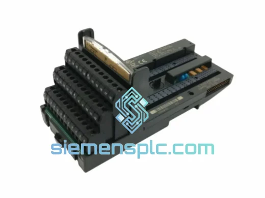
GE IC200MDL940F Relay Output Module – VersaMax Series
Request verified availability, condition, replacement risk review, packing options and courier lead time for IC200MDL940F.
BrandGE Automation & Controls
Part NumberIC200MDL940F
ConditionAvailability Check
Lead TimeRFQ Confirmation
DocumentsDatasheet / photos by RFQ
ShippingExport packing available
Auto-filled RFQ
IC200MDL940F
Click Request Quote and the part number is inserted into the inquiry form automatically.
- Reply by email: [email protected]
- WhatsApp / Tel: +86 18359268345
- Mon-Sat 9:00-18:00 GMT+8
Procurement Data
Key Product Information
Core fields for model confirmation and RFQ routing. Detailed product narrative remains below.
- Brand
- GE Automation & Controls
- Primary Part Number
- IC200MDL940F
- Product Type
- PLC Relay Output Module
- Series / Family
- VersaMax
- Manufacturer
- GE Automation & Controls (formerly GE Fanuc)
- Country of Origin
- US
- Catalog Category
- I/O Modules
- Operating Temp.
- 0°C to +60°C
- Warranty
- 12 months from date of shipment
Model confirmed for inquiry
IC200MDL940F
Send quantity, destination and urgency. The RFQ form keeps this part number attached.
Request Quote
Product Overview
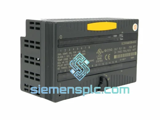
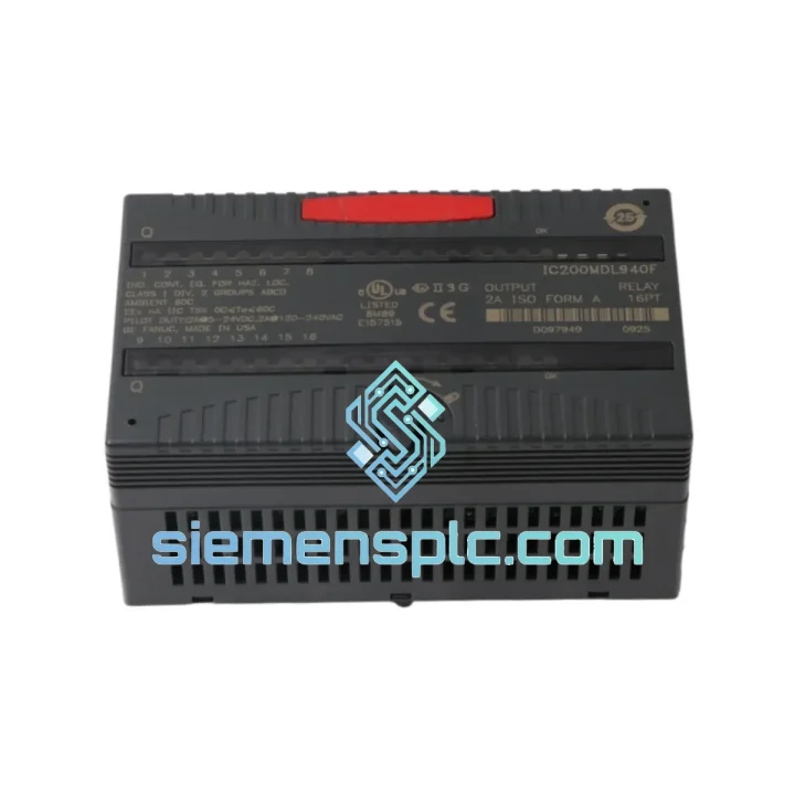
GE IC200MDL940F: 8-Point Relay Output Module for VersaMax Modular I/O Systems
The IC200MDL940F is a discrete relay output module designed for deployment within GE’s VersaMax Modular I/O platform. It provides eight independently switched relay contacts capable of driving both AC and DC field loads across a broad voltage envelope. In a distributed control architecture, this module occupies a single slot on a VersaMax carrier and communicates with the host CPU via the VersaMax backplane bus, delivering deterministic output switching with full galvanic isolation between the logic domain and the field wiring domain.
Each relay contact is rated at 2 A continuous for resistive loads, with a switching voltage range of 5–250 V AC or 5–30 V DC. This dual-voltage capability makes the IC200MDL940F suitable for mixed-panel environments where both 24 V DC solenoid valves and 120/240 V AC motor starters must be controlled from a single I/O rack without additional interposing relays. The module’s mechanical relay architecture provides true galvanic isolation — there is no shared return path between field circuits — which is a critical design requirement in installations subject to ground loops or high common-mode noise.
Real-time Stock & RFQ: [email protected] | WhatsApp: +86 18359268345
Technical Parameters
| Parameter | Value |
|---|---|
| Part Number / SKU | IC200MDL940F |
| Manufacturer | GE Automation & Controls (formerly GE Fanuc) |
| Series | VersaMax Modular I/O |
| Module Type | Discrete Relay Output |
| Output Points | 8 (Form A, SPST-NO contacts) |
| Output Current Rating | 2 A per point (resistive); 0.5 A per point (inductive) |
| Switching Voltage Range | 5–250 V AC / 5–30 V DC |
| Isolation Type | Mechanical relay (galvanic isolation, field-to-logic) |
| Minimum Switching Load | 10 mA @ 5 V DC |
| Relay Mechanical Life | ≥ 10,000,000 operations (no load) |
| Relay Electrical Life | ≥ 100,000 operations at rated load |
| Backplane Interface | VersaMax standard I/O bus |
| Operating Temperature | 0°C to +60°C |
| Storage Temperature | -40°C to +85°C |
| Relative Humidity | 5–95% non-condensing |
| Module Weight | Approx. 510 g |
| Certifications | CE (LVD), UL Listed, cUL, RoHS |
| Warranty | 12 months from date of shipment |
Hardware Logical Analysis
The IC200MDL940F implements a relay-per-point architecture rather than a shared-contact matrix, meaning each of the eight output channels operates on an independent electromechanical relay coil and contact set. This design eliminates cross-channel leakage current — a failure mode common in solid-state output modules where OFF-state leakage can inadvertently energize high-impedance field devices such as proximity sensors wired in series with relay coils.
EMC and Transient Suppression: The relay coil drive circuitry incorporates flyback diodes on the logic side to suppress inductive kickback when the coil de-energizes. On the field side, the open contact architecture means the module itself introduces no snubber network into the field circuit, which is intentional — it allows the system designer to select load-appropriate RC snubbers or MOV clamps externally, avoiding the thermal derating issues that arise when internal snubbers must absorb energy from large inductive loads repeatedly.
Backplane Bus Interaction: The module communicates with the VersaMax CPU or remote I/O head via the backplane’s parallel I/O bus. Output state data is latched in the module’s local output register and driven to the relay coils through an optocoupler stage that provides a second isolation barrier between the backplane logic (3.3 V / 5 V domain) and the relay coil drive circuit (typically 12 V DC internal). This two-stage isolation — optocoupler plus mechanical contact — yields a total field-to-logic isolation withstand voltage exceeding 1,500 V AC, which satisfies IEC 61131-2 requirements for Type 2 digital output modules.
Fault Transparency: The IC200MDL940F does not incorporate internal current sensing on the output contacts. This is a deliberate architectural choice consistent with GE’s VersaMax philosophy of keeping relay output modules simple and deterministic. Fault detection (open load, welded contact) is the responsibility of the field wiring design — typically implemented via feedback input points wired to auxiliary contacts on downstream contactors. This approach avoids false fault trips caused by capacitive load inrush and is preferred in high-reliability MRO environments where nuisance trips carry significant production cost.
System Integration Benefits
The IC200MDL940F delivers the following measurable advantages when integrated into a VersaMax-based control system:
- Zero-leakage OFF-state isolation: Mechanical contacts present true open-circuit impedance in the OFF state, eliminating the 1–5 mA leakage current inherent in TRIAC or transistor output modules. This is essential when driving relay coils with low hold-in current thresholds.
- Mixed-voltage field wiring from a single rack: The 5–250 V AC / 5–30 V DC range allows a single module to control both 24 V DC solenoids and 120 V AC pilot lights within the same I/O slot, reducing rack count and wiring complexity.
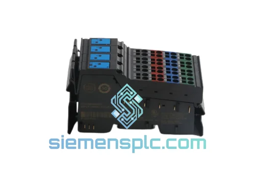
- Drop-in slot compatibility: The module conforms to the VersaMax single-slot form factor and is electrically compatible with IC200CHS002, IC200CHS005, and IC200CHS022 carriers, enabling field replacement without carrier modification or software reconfiguration beyond I/O table updates.
- Deterministic scan-cycle output latency: Output state changes are applied at the end of each CPU scan cycle with a relay operate time of ≤ 10 ms (energize) and ≤ 5 ms (de-energize), providing predictable timing margins for interlock logic design.
- High mechanical relay endurance for MRO environments: With ≥ 10 million mechanical operations, the module is suited for high-cycle applications such as conveyor indexing and packaging machine sequencing without scheduled relay replacement within normal equipment service intervals.
- Simplified diagnostic loop design: Because each output point is independent, diagnostic feedback can be implemented per-channel using auxiliary contacts on downstream devices, giving the CPU full visibility into field-side contact state without shared-bus ambiguity.
- Reduced panel heat load: Relay output modules dissipate field-side switching energy in the load and contact, not in semiconductor junctions within the module. At partial load, the IC200MDL940F’s internal power dissipation is lower than equivalent solid-state output modules driving the same resistive loads, contributing to lower panel ambient temperature and extended component life.
- Compatibility with GE Proficy Machine Edition: The module is fully enumerated in the VersaMax hardware catalog within Proficy ME Logic Developer, enabling drag-and-drop I/O configuration, automatic address assignment, and integrated online diagnostics without manual register mapping.
Quality Assurance & Global Logistics
Every IC200MDL940F unit supplied by siemensplc.com is sourced through verified industrial distribution channels. Units undergo a structured pre-shipment inspection covering part number label authentication, physical integrity assessment (connector pins, housing, revision markings), and where feasible, powered functional verification of relay coil energization and contact switching against GE’s published electrical specifications.
All shipments originate from our warehouse in Xiamen, China — a major logistics hub with direct access to international express carriers including DHL, FedEx, and UPS, as well as consolidated sea freight services for bulk orders. Typical transit times are 3–5 business days for express air freight to Europe, North America, Southeast Asia, and the Middle East. Export documentation — commercial invoice, packing list, certificate of origin, and HS code declaration (8537.10) — is prepared for every international shipment to facilitate smooth customs clearance.
Each unit is packed in anti-static shielding bags with foam-lined cartons to prevent mechanical shock damage during transit. A 12-month warranty covers manufacturing defects and verified functional failures under normal operating conditions. Warranty claims are processed with a target response time of 48 business hours from receipt of the defective unit.
Contact Information
Email: [email protected]
WhatsApp: +86 18359268345
Web: siemensplc.com
Location: Xiamen, China
© 2026 siemensplc.com. All rights reserved.
Ready to quote
[email protected]
Send This Part Number to Sales
RFQ workflow
Quality workflow ->
Confirmation Process
01Model confirmation
We check the full part number, brand, series and visible nameplate information before quotation.
02Availability reply
Sales confirms stock path, condition option, quantity and realistic lead time for export dispatch.
03Packing & courier
DHL, FedEx, UPS or buyer courier arrangements can be reviewed with packing requirements.
Continue sourcing
Browse full catalog ->
Related Automation Parts
Similar brand or category products for fast comparison and multi-item RFQ lists.
GE Automation & Controls
RFQ Ready
GE IC200UDD104-BG Programmable Logic Controller
VersaMax
Origin US
Programmable Logic Controller
GE Automation & Controls
RFQ Ready
GE IC220MDL643 Digital Input Module
VersaMax
Origin US
PLC Digital Input Module
GE Automation & Controls
RFQ Ready
GE IC200CHS022 Compact I/O Carrier
VersaMax
Origin US
PLC I/O Carrier