GE
RFQ Ready
GE IS420UCSDH1 Servo Drive Controller Module
Mark VI
Origin US
Servo Drive Controller Module
Request verified availability, condition, replacement risk review, packing options and courier lead time for IS200DSFCG1AEB.
Click Request Quote and the part number is inserted into the inquiry form automatically.
Core fields for model confirmation and RFQ routing. Detailed product narrative remains below.
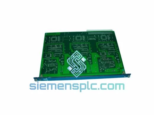
The IS200DSFCG1AEB is a dedicated driver shunt current feedback board within GE’s IS200 module family, engineered specifically for deployment inside the Mark VI and Mark VIe turbine control systems. Its primary function is to close the current-sensing loop between the excitation driver stage and the Mark VI VME-based controller, delivering a conditioned analog feedback signal that the controller uses to regulate output current with sub-millisecond correction latency. Without accurate shunt feedback, the controller operates open-loop on the driver stage — a condition that leads to excitation instability, protective relay actuation, and forced turbine trip.
In a Mark VI architecture, the IS200DSFCG1AEB mounts in the I/O expansion rack and interfaces with the terminal board assembly via a dedicated ribbon or backplane connector. The board samples the voltage drop across a precision low-resistance shunt element — typically in the milliohm range — and amplifies the differential signal through an instrumentation amplifier stage with a common-mode rejection ratio (CMRR) exceeding 80 dB. This level of CMRR is necessary because the shunt sits in a high-current path where ground-referenced noise from switching transients can reach several hundred millivolts. The amplified signal is then filtered, scaled, and presented to the VME backplane as a 0–10 V or 4–20 mA analog output, depending on the rack configuration.
The board’s signal chain is designed around a differential input topology with galvanic isolation between the shunt measurement circuit and the logic-side output. This isolation barrier — implemented via precision isolation amplifiers rated to at least 500 V DC working isolation — prevents ground loops from corrupting the feedback signal and protects the controller backplane from fault voltages originating in the power stage. The isolation stage also satisfies the functional safety requirements of IEC 61511 SIL 2 installations, which are common in gas turbine-driven compressor trains in the oil and gas sector.
Thermal management on the IS200DSFCG1AEB is handled through a combination of low-power component selection and copper pour heat spreading on the PCB. The instrumentation amplifier and isolation amplifier ICs are specified for an operating junction temperature range of −40 °C to +125 °C, ensuring stable gain characteristics across the full ambient temperature envelope of a turbine control enclosure, which can reach 55 °C continuous in tropical installations. Gain drift over temperature is controlled to less than 25 ppm/°C, which at a full-scale output of 10 V corresponds to a maximum drift of 250 µV/°C — well within the ±0.1% full-scale accuracy budget of the Mark VI analog input subsystem.
The board is compatible with the full IS200 rack ecosystem, including the TBAIH1C terminal board and the VCRCH1BBB VME controller card. It draws logic-side power from the rack’s +5 V and ±15 V rails, with a total power consumption under 2.5 W in normal operation. The field-side isolation supply is derived internally from the +24 V field power bus, eliminating the need for an external isolated supply and simplifying installation in retrofit scenarios where the original wiring harness is reused.
Real-time Stock & RFQ: [email protected] | WhatsApp: +86 18359268345
| Parameter | Value / Specification |
|---|---|
| Part Number | IS200DSFCG1AEB |
| Manufacturer | GE (General Electric) |
| Series | IS200 / Mark VI Turbine Control System |
| Function | Driver Shunt Current Feedback Monitoring |
| Input Signal Type | Differential voltage across precision shunt resistor |
| Output Signal | 0–10 V DC / 4–20 mA (rack-configured) |
| Common-Mode Rejection Ratio (CMRR) | ≥ 80 dB @ 50/60 Hz |
| Isolation Voltage (Field-to-Logic) | 500 V DC working isolation |
| Gain Temperature Drift | < 25 ppm/°C |
| Operating Temperature | 0 °C to +55 °C (ambient, rack-mounted) |
| Component Temperature Rating | −40 °C to +125 °C (junction) |
| Logic Supply Voltage | +5 V, ±15 V (from VME rack) |
| Field Supply Voltage | +24 V DC (field power bus) |
| Power Consumption | < 2.5 W (normal operation) |
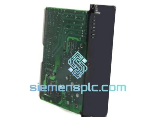
| Form Factor | PCB plug-in module, IS200 rack format |
| Weight | 430 g |
| Compatible Controllers | GE Mark VI, Mark VIe |
| Compatible Terminal Board | IS200TBAIH1C and equivalents |
| Functional Safety | Suitable for IEC 61511 SIL 2 installations |
| Warranty | 12 months from date of shipment |
The IS200DSFCG1AEB’s hardware design addresses three distinct engineering challenges that are specific to shunt-based current measurement in high-power turbine drive circuits.
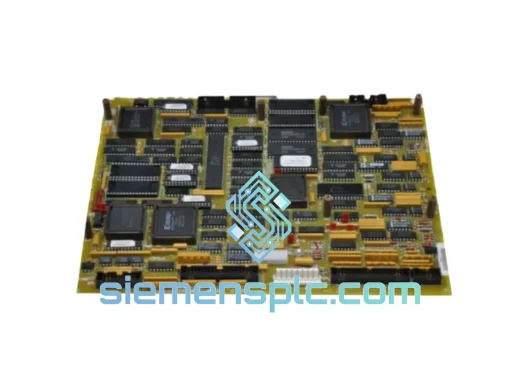
Differential Measurement with High Common-Mode Rejection: The shunt element sits in a conductor carrying tens to hundreds of amperes. Both terminals of the shunt float at the potential of the power bus, which can be several hundred volts above the control system ground. The board’s input stage uses a precision instrumentation amplifier configured for a differential gain of 10–100 (depending on the shunt resistance value), with matched resistor networks laser-trimmed to 0.01% tolerance. This matching is the primary mechanism for achieving the ≥80 dB CMRR specification. Any mismatch in the resistor network directly degrades CMRR and introduces a common-mode error proportional to the bus voltage — a critical failure mode that the laser-trimmed network eliminates.
Galvanic Isolation Architecture: After the instrumentation amplifier stage, the signal passes through a precision isolation amplifier. This component uses a capacitive or transformer-based coupling mechanism to transfer the analog signal across the isolation barrier without a direct electrical path. The isolation barrier rating of 500 V DC working voltage provides a safety margin well above the typical 24–48 V DC field bus voltages encountered in Mark VI installations, while also protecting against transient overvoltages generated by inductive switching in the driver stage. The isolation amplifier’s nonlinearity is specified at less than 0.01%, preserving the measurement accuracy established by the input stage.
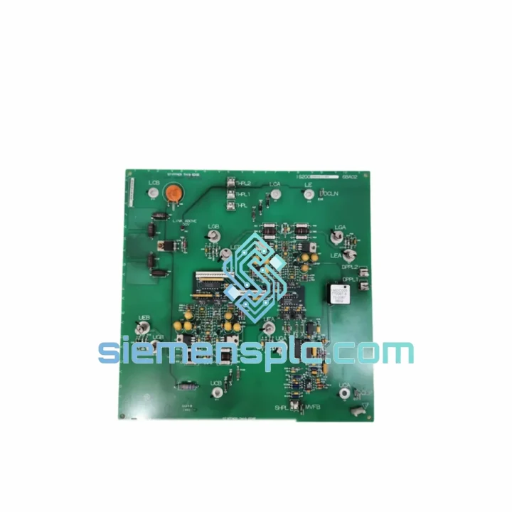
EMC Design and Conducted Noise Immunity: The PCB layout separates the high-impedance analog input traces from the digital logic and power supply sections using a split ground plane with a single-point connection at the isolation barrier. Bypass capacitors are placed within 2 mm of each IC power pin, with a combination of 100 nF ceramic and 10 µF tantalum capacitors to suppress both high-frequency switching noise and lower-frequency ripple from the rack power supply. The board meets IEC 61000-4-4 (electrical fast transient) and IEC 61000-4-5 (surge immunity) requirements, which are mandatory for equipment installed in turbine control enclosures subject to switching transients from high-voltage contactors and motor starters in the same electrical room.
Redundancy Arbitration Compatibility: In Mark VI TMR (Triple Modular Redundancy) configurations, three IS200DSFCG1AEB boards may be installed in parallel, each feeding an independent controller voter. The board’s output impedance is designed to be high enough that a single board failure (open-circuit output) does not load the remaining two boards’ outputs, preserving the 2-of-3 voting logic integrity. This passive fault tolerance is a deliberate design choice that avoids the need for active fault isolation circuitry on the feedback board itself.
Every IS200DSFCG1AEB unit supplied through siemensplc.com is sourced as genuine GE-manufactured hardware. Units are not rebranded, cloned, or third-party manufactured. Each board carries the original GE part number label, revision marking, and date code traceable to GE’s manufacturing records.
Before dispatch, each unit undergoes a structured inspection protocol: visual examination of the PCB for component damage, solder joint integrity, and connector condition; continuity verification of the isolation barrier; and functional power-on testing to confirm the analog output responds correctly to a simulated differential input signal. Units that do not pass all inspection stages are quarantined and not offered for sale.
Shipping is handled from our warehouse in Xiamen, China, using DHL Express, FedEx International Priority, and UPS Worldwide Express services. Transit times to major industrial hubs are typically 3–5 business days to Europe, 4–6 business days to North America, and 2–4 business days to Southeast Asia and the Middle East. All shipments include full export documentation — commercial invoice, packing list, and certificate of origin — to facilitate customs clearance in destination countries. ESD-safe anti-static packaging and foam-lined outer cartons are used for all board shipments to prevent transit damage.
A 12-month warranty covers all units against defects in materials and workmanship under normal operating conditions. Warranty claims are processed with a target response time of 48 hours, and replacement units are dispatched from stock where available to minimize the customer’s system downtime.
Email: [email protected]
WhatsApp: +86 18359268345
Web: siemensplc.com
Location: Xiamen, China
© 2026 siemensplc.com. All rights reserved.
We check the full part number, brand, series and visible nameplate information before quotation.
Sales confirms stock path, condition option, quantity and realistic lead time for export dispatch.
DHL, FedEx, UPS or buyer courier arrangements can be reviewed with packing requirements.
Similar brand or category products for fast comparison and multi-item RFQ lists.